Reverse multi-angle blowing and drying device

A drying device, multi-angle technology, applied in the direction of drying gas arrangement, spraying device, spraying device, etc., can solve the problems of affecting the cooling effect, heavy drying device, cooling water residue, etc., to promote the combined discharge of water and gas, and the combination is fast and accurate , Finished surface smooth effect

Inactive Publication Date: 2017-08-15
宁波奇尘电子科技有限公司
View PDF7 Cites 4 Cited by
  • Summary
  • Abstract
  • Description
  • Claims
  • Application Information

AI Technical Summary

Problems solved by technology

[0003] However, the traditional purging and drying device has the following disadvantages: 1) The integral structure design makes the drying device too heavy, which is not conducive to daily operation, replacement and cleaning; 2) There is no design of decompression and diversion tank, and the combined discharge of water and air is not smooth , the surface effect of the steel body needs to be improved; 3) The design of the front blowing nozzle, the blowing nozzle is located at the front of the drying device, due to the reaction force generated during the high-speed blowing process, the cooling water is brought into the dryer, affecting the cooling effect; 4) Bolts are used for installation and positioning. Although the fastness is guaranteed, it is inconvenient and flexible to replace
This application has strengthened the cooling effect on the surface of the wire rod to a certain extent, but the combined discharge of water and air in the reverse purge structure of the application is not smooth, resulting in poor cooling effect, and the cooling water on the surface of the wire rod still partially remains. In the end, the surface is not purged cleanly, and the red steel is not cooled uniformly, so the cooling effect of the steel surface needs to be improved.

Method used


Image

  • Reverse multi-angle blowing and drying device
  • Reverse multi-angle blowing and drying device
  • Reverse multi-angle blowing and drying device

Examples


Embodiment 2

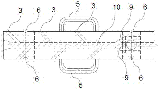
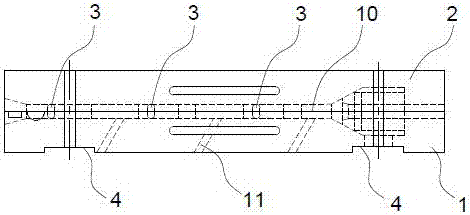
[0034] A kind of reverse multi-angle purging and drying device of this embodiment, its basic structure is the same as that of Embodiment 1, and there are 6 decompression splitter grooves 3 distributed asymmetrically on both sides of the steel hole 10, and every two adjacent different The side decompression shunt grooves 3 are one group, and there are 3 groups in total. The difference is that the angle between the axial direction of the decompression shunt groove 3 and the axial direction of the steel hole 10 is 45°, that is, in the decompression shunt groove 3 The angle between the flow direction of the compressed air and the reverse direction of rolling is 45°, the distance between the decompression shunt trough 3 adjacent to the same side of the steel hole 10 and the junction of the steel hole 10 is 120 mm, and the distance between the adjacent pressure relief grooves 3 on the same side of the steel hole 10 is 120 mm. The distance between the junctions of the pressure splitte...

Embodiment 3

[0036] A kind of reverse multi-angle purging and drying device of this embodiment, its basic structure is the same as that of Embodiment 1, and there are 6 decompression splitter grooves 3 distributed asymmetrically on both sides of the steel hole 10, and every two adjacent different The side decompression shunt grooves 3 form a group, and there are 3 groups in total. The difference is that the angle between the axial direction of the decompression shunt groove 3 and the axial direction of the steel hole 10 is 55°, that is, in the decompression shunt groove 3 The included angle between the flow direction of the compressed air and the reverse direction of rolling is 55°, the distance between the decompression shunt trough 3 adjacent to the same side of the steel hole 10 and the junction of the steel hole 10 is 150mm, and the adjacent pressure reduction groove 3 on the same side of the steel hole 10 is 150mm. The distance between the junctions of the pressure splitter grooves 3 a...


PUM


Abstract

The invention discloses a reverse multi-angle blowing and drying device and belongs to the field of rolling equipment. The reverse multi-angle blowing and drying device comprises pressure-reduction flow distribution grooves, positioning grooves, handles, upper-lower frame fixing grooves, fixing lugs, air inlet holes, blowing nozzles and a steel hole. The air inlet holes are located in the tail of a bottom frame. The blowing nozzles communicate with the air inlet holes. Each blowing nozzle is a conical open 360-degree ring-shaped beam nozzle with a leftward opening. According to the reverse multi-angle blowing and drying device, the direction of compressed air sprayed by the blowing nozzles is opposite to the rolling direction; semicircular grooves in the central axis of the bottom frame and semicircular grooves in the central axis of a top frame are combined into the steel hole; the steel hole communicates with the blowing nozzles, the pressure-distribution flow distribution grooves are distributed in the two sides of the steel hole, and the pressure-distribution flow distribution grooves are formed by combining the corresponding grooves in the bottom frame and the corresponding grooves in the top frame; and the design of the rear-arranged blowing nozzles is adopted, the crossed release manner is adopted, and water and gas are promoted to be combined and discharged smoothly, so that the surface of red steel is free of cooling water local residues, and the surface of a steel body is uniformly cooled.

Description

technical field [0001] The invention belongs to the field of steel rolling equipment, and more specifically relates to a reverse multi-angle purge drying device, which is a drying device for purging the surface of wire rods during high-speed wire rod rolling. Background technique [0002] At present, in the domestic high-speed wire rolling equipment, the structure of the water-cooling equipment is roughly the same, that is, in a group of water-cooling equipment, there are 9 water spray cooling devices, 2 water stripping devices and 1 gas purging and drying device. The distribution is: water spray cooling device, water stripping device and gas purging drying device. The principle is: after the high-speed wire rod is rolled at high speed by the rolling mill in the rolling direction, the temperature of the wire rod body rises, and it needs to be cooled by water to maintain the material requirements of the finished wire rod. At this time, the water spray cooling device works to ...

Claims


Application Information

Patent Timeline
Patent Type & Authority Applications(China)
IPC IPC(8): B21B45/02F26B21/00B05B1/06
CPCB21B45/0281B05B1/06F26B21/004
Inventor 叶力黄崇军
Owner 宁波奇尘电子科技有限公司
Why Eureka
Try Eureka