
Improved welding robot and welding method thereof

A technology for welding robots and welding parts, applied in welding equipment, resistance welding equipment, cooling electrodes, etc., can solve the problems of scrapped workpieces, high welders, roller electrodes cannot be placed in the welding position, etc., to achieve good welding, reduce heat generation, The effect of improving the melting effect

Pending Publication Date: 2017-08-15
赖连容
View PDF0 Cites 0 Cited by
  • Summary
  • Abstract
  • Description
  • Claims
  • Application Information

AI Technical Summary

Problems solved by technology

However, the welding position of some specific workpieces is at the gap between two metal sheets, the position is narrow, the roller electrode used in seam welding cannot be placed in the welding position, and the traditional spot welding equipment cannot weld long welds. Therefore, this kind of welding work is manual welding, which requires high technical requirements for welders, and is prone to scrapping workpieces due to human errors.

Method used


Image

  • Improved welding robot and welding method thereof
  • Improved welding robot and welding method thereof
  • Improved welding robot and welding method thereof

Examples


Embodiment Construction

[0029] The standard parts used in the present invention can be purchased from the market, and the special-shaped parts can be customized according to the instructions and the accompanying drawings. The specific connection methods of each part adopt mature bolts, rivets, welding in the prior art , pasting and other conventional means, no longer described in detail here.

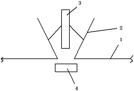
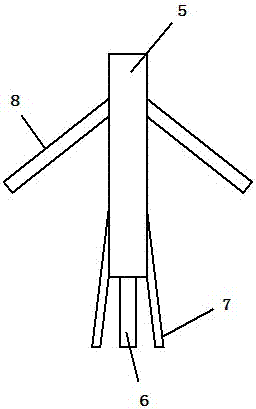
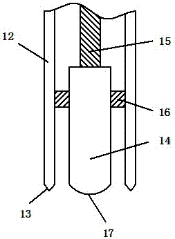
[0030] refer to Figure 1-9 , a specific embodiment of the present invention comprises a frame 1, a mold side plate 2 is arranged on the frame 1, a gap 5 is arranged between the mold side plates 2, an electric welding positive electrode 3 is arranged above the mold side plate 2, and the mold side plate 2 The electric welding negative pole 4 is arranged below the electric welding positive pole 3 and the electric welding negative pole 4 are arranged on the drive mechanism (not shown in the figure) respectively; Both sides of the electrode 6 are provided with a second electrode 7, and the installation rod 5 is a...


PUM


Abstract

The invention discloses an improved welding robot comprising a rack. Die side plates are arranged on the rack. A gap is arranged between the die side plates. Electrowelding anodes are arranged above the die side plates. Electrowelding cathodes are arranged below the die side plates. The electrowelding anodes and the electrowelding cathodes are arranged on drive mechanisms correspondingly. Each electrowelding anode comprises an installation rod, wherein a first electrode is arranged at the bottom of the installation rod, second electrodes are arranged on the two sides of the first electrode, and two pneumatic support rods are further arranged on the installation rod. Each electrowelding cathode comprises an installation plate, wherein a third electrode is arranged on the installation plate, and a plurality of cooling water circulating tubes are arranged on the two sides of the third electrode. The invention further discloses a welding method of the welding robot. Through the improved welding robot and the welding method thereof, the deficiencies of the prior art can be overcome, and automatic welding of a weld joint in a narrow bent position is achieved.

Description

technical field [0001] The invention relates to the technical field of welding equipment, in particular to an improved welding robot and a welding method thereof. Background technique [0002] Welding is a general technique applied to the joining of metal parts. Among them, resistance welding is to apply a welding current at the welding position, and use the heat generated by the current flowing through the welding position to realize the melting and welding of the welding position. For welding positions with longer weld seams and thinner metal thicknesses, seam welding is generally used in the prior art for welding. However, the welding position of some specific workpieces is at the gap between two metal sheets, the position is narrow, the roller electrode used in seam welding cannot be placed in the welding position, and the traditional spot welding equipment cannot weld long welds. Therefore, this kind of welding work is manual welding, which requires high technical req...

Claims


Application Information

Patent Timeline
IPC IPC(8): B23K11/31B23K11/30B23K11/10B23K11/08
CPCB23K11/08B23K11/10B23K11/3054B23K11/31
Inventor 赖连容
Owner 赖连容
Learn More