
Automatic test system of airborne receiver

An automatic test system and receiver technology, applied to radio wave measurement systems, instruments, etc., can solve problems such as low test coverage, inability to automatically record data, low test efficiency, etc., achieve strong scalability, improve test efficiency, and save energy the effect of time

Active Publication Date: 2017-08-15
BEIJING INST OF RADIO MEASUREMENT
View PDF8 Cites 0 Cited by
  • Summary
  • Abstract
  • Description
  • Claims
  • Application Information

AI Technical Summary

Problems solved by technology

[0004] The technical problem to be solved by the present invention is: in the prior art, the personnel who test the airborne receiver need to use a manual test method to conduct spot checks on several frequency points of a certain channel, which not only requires repeated plugging and unplugging of cables, but also cannot automatically Record data, resulting in low test coverage and low test efficiency

Method used


Image

  • Automatic test system of airborne receiver
  • Automatic test system of airborne receiver

Examples


Embodiment 1

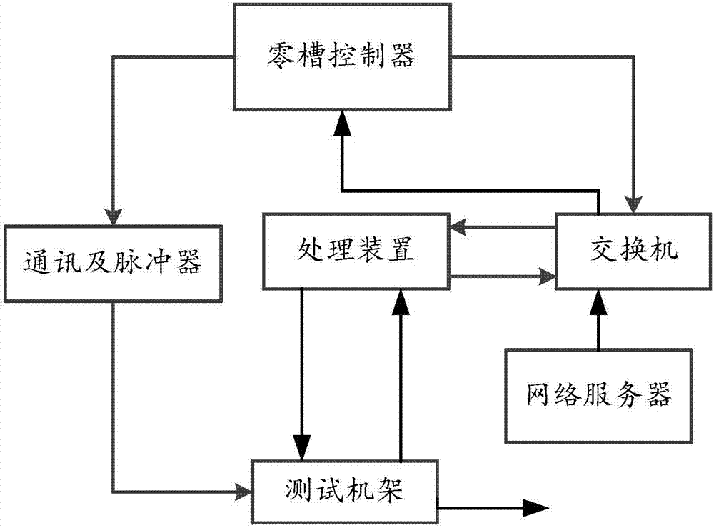
[0035] like figure 1 Shown, a kind of airborne receiver automatic test system in this example 1, this system comprises: zero slot controller 4, switchboard 13, processing device, test frame 17, communication and pulser 2; The controller 4 is used to send the DC power supply command and the microwave excitation signal command to the switch 13, and also sends the communication and pulse command to the communication and pulser 2; the switch 13 is used to send the received DC power supply command, The microwave excitation signal command is forwarded to the processing device; the processing device is used to analyze the DC power supply command and output direct current to the test rack 17 according to the resolved DC power supply command; the processing device is also used to analyze the microwave excitation signal command and According to the microwave excitation signal command after the analysis, the channel corresponding to the order is controlled to open, thereby outputting the...

Embodiment 2

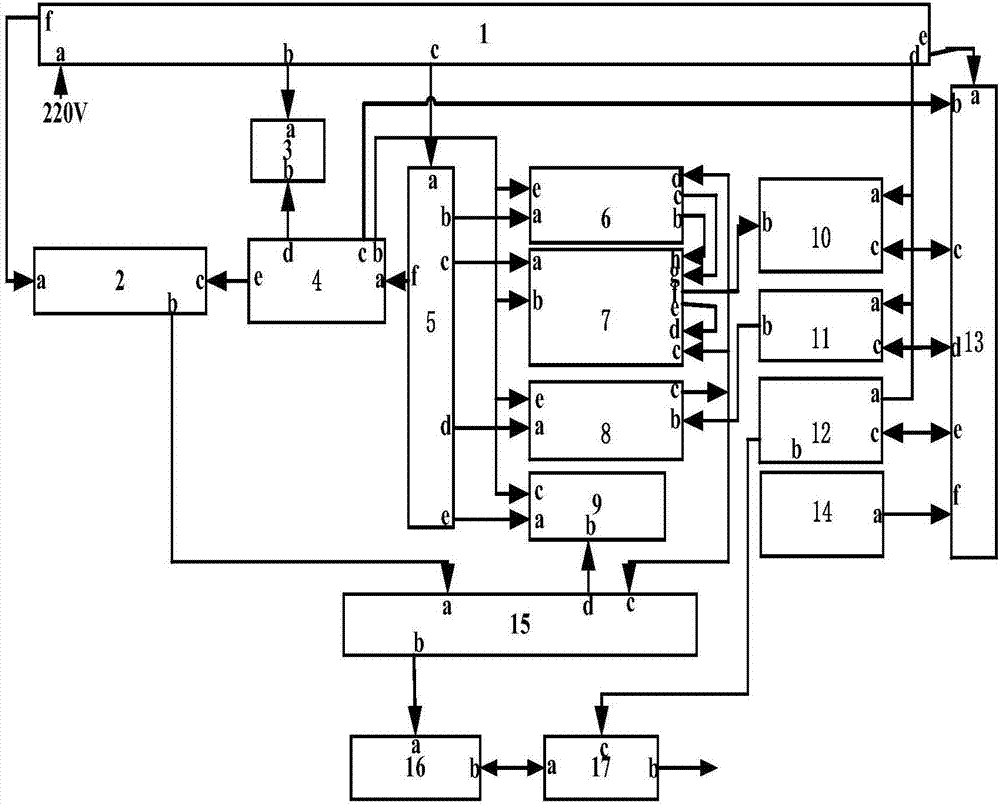
[0062] like figure 2 As shown, a kind of airborne receiver automatic test system in the present embodiment 2, this system comprises: network server 14, distributor 1, zero slot controller 4, display 3, spectrum analyzer 10, microwave signal source 11, Communication and Pulser 2, Switch 13, PXI Chassis 5, Dual 6 to 2 Microwave Switch A6, Dual 6 to 2 Microwave Switch B7, 12 to 1 Microwave Switch 8, Oscilloscope 9, Test Rack 17, Receiver 15 and Adapter 16 ;

[0063] The input terminal a of distributor 1 is connected to the 220V power supply voltage, the power supply output terminal b of distributor 1 is connected to the power supply input terminal a of display 3, the power supply output terminal c of distributor 1 is connected to the power supply input terminal a of PXI chassis 5, and distributor 1 The power supply output d of the spectrum analyzer 10 is connected with the power supply input a of the spectrum analyzer 10, the power supply input a of the microwave signal source ...


PUM


Abstract

The invention relates to an automatic test system of an airborne receiver. The system is composed of a zero-slot controller, a switch, a processing device, a test rack, and a communication and pulser unit. The zero-slot controller is used for sending a direct-current power supply command and a microwave excitation signal command to the switch and also sending a communication and pulse command to the communication and pulser unit. The switch is used for forwarding the commands to the processing device. The processing device is used for parsing the direct-current power supply command and the microwave excitation signal command and outputting a direct current and signal to the test rack. The communication and pulser unit is used for parsing the communication and pulse command and outputting a communication and pulse signal to the test rack. And the test rack transfers the signals to an airborne receiver. With the zero-slot controller, testing programs can be loaded, so that full-automatic testing of multi-channel multi-frequency-point testing projects can be realized; and the test data are stored automatically, so that the test efficiency can be improved. Network controlling and test data reading are realized by a network server.

Description

technical field [0001] The invention belongs to the field of airborne radar equipment, in particular to an airborne receiver automatic test system. Background technique [0002] Airborne receiver is an important part of airborne radar equipment, and its performance parameters and indicators directly affect the combat effectiveness of the entire radar. When mass-producing receivers, multiple indicators such as frequency, power, noise figure, phase noise, channel isolation, and image rejection of multiple channels of the receiver need to be tested to verify and evaluate the function and performance of the receiver index. [0003] At present, the system for testing airborne receivers usually includes: general-purpose test instruments (including microwave signal sources, spectrum analyzers), test racks, and DC power supplies, but the personnel who test airborne receivers need to manually test the Spot checks are performed at several frequency points, which not only requires re...

Claims


Application Information

Patent Timeline
Patent Type & Authority Applications(China)
IPC IPC(8): G01S7/40
CPCG01S7/4021
Inventor 吴来萍陈利彬
Owner BEIJING INST OF RADIO MEASUREMENT
Learn More