LED drive chip capable of improving thyristor dimmer compatibility and circuit

A technology of LED driving and dimmer, applied in the field of LED driving, can solve the problems of increasing chip cost, affecting efficiency, increasing area and cost, etc., and achieving the effect of increasing input current, improving efficiency and reducing loss

Active Publication Date: 2017-08-15
SHANGHAI ORIENT CHIP TECH CO LTD
View PDF5 Cites 17 Cited by
  • Summary
  • Abstract
  • Description
  • Claims
  • Application Information

AI Technical Summary

Problems solved by technology

[0006] (1) The MOS tube M0' must be a high-pressure tube, which increases the area and cost
[0007] (2) The input current increased by the pull-down of the MOS transistor M0' flows directly to the ground through the current limiting resistors R1' and M0', which increases the loss and affects the efficiency
On this basis, if the high-voltage MOS transistor M0' is set outside the chip as a peripheral circuit, the system cost will be increased. At the same time, the output terminal of the amplifier 21' must be connected to the high-voltage MOS transistor M0' through the external pin of the chip, so the chip must In addition, a pin is added, which increases the cost of the chip; if the high-voltage MOS transistor M0' is integrated in the chip, the output terminal of the amplifier 21' can be directly connected to the gate of the high-voltage MOS transistor M0', but the high-voltage MOS transistor 21' The drain must be connected to the bus outside the chip connected to the positive output terminal of the rectifier circuit 12' through the resistor R1', so the chip still needs to add an extra pin

Method used


Image

  • LED drive chip capable of improving thyristor dimmer compatibility and circuit
  • LED drive chip capable of improving thyristor dimmer compatibility and circuit
  • LED drive chip capable of improving thyristor dimmer compatibility and circuit

Examples


Embodiment Construction

[0050] Below, according to the accompanying drawings, preferred embodiments of the present invention are given and described in detail, so that the functions and features of the present invention can be better understood.

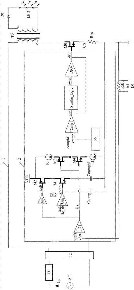
[0051] Such as figure 2As shown, an LED drive circuit of the present invention that improves compatibility with silicon controlled dimmers includes a peripheral circuit 1 and an LED drive chip 2 . Among them, the peripheral circuit 1 is a general circuit, which includes AC power supply AC, thyristor dimmer 11, rectifier circuit 12, transformer T0, output voltage sampling resistor Rcs, power MOS tube M0, freewheeling diode D0, LED load, input Current sampling resistor Rdet and clamping diode D1; LED driver chip 2 is the core of the present invention, which includes a hysteresis comparator 21, a transconductance module Gm, a first inverter Inv1, a compensation capacitor Ccomp, an isolation capacitor Ccompbf, a first NMOS Tube M1, second NMOS tube M4, first ...


PUM


Abstract

The invention provides an LED drive chip capable of improving the thyristor dimmer compatibility and a circuit. The chip is connected with a peripheral circuit including a thyristor dimmer and an input current sampling resistor. The chip comprises a hysteresis comparator, a transconductance module, a first NMOS tube, a first PMOS tube, a second PMOS tube, a second NMOS tube, a compensation capacitor, an isolation capacitor, a first comparator and a drive module. According to the invention, the input current is increased without directly pulling down the bus voltage Vin; a part where the input current is increased is used as a part of output current; compared with the figure 1 in the prior art, the chip has remarkably improved efficiency, and particularly in the case of small output current, the efficiency is remarkably improved; and in addition, the cost is reduced without using a high voltage MOS tube and additionally increasing chip pins.

Description

technical field [0001] The invention relates to the field of LED driving, in particular to an LED driving chip and a circuit that improve compatibility with silicon controlled dimmers. Background technique [0002] As a dimming device for traditional lighting fixtures, the thyristor dimmer has the advantages of low cost, simple and reliable circuit, and good dimming effect. Therefore, the thyristor dimmer has become the most widely used dimming device for traditional lighting fixtures such as incandescent lamps. As LED lamps gradually replace traditional lighting fixtures, the market requires that LED drive circuits must also be compatible with thyristor dimmers. [0003] Since traditional lighting fixtures such as incandescent lamps are resistive loads, thyristor dimmers have natural adaptability to resistive loads. The LED is a current-driven load. When the LED current is small and the input current of the drive circuit is lower than the holding current of the thyristor ...

Claims


Application Information

Patent Timeline
Patent Type & Authority Applications(China)
IPC IPC(8): H05B33/08H05B44/00
CPCH05B45/37Y02B20/30
Inventor 不公告发明人
Owner SHANGHAI ORIENT CHIP TECH CO LTD
Why Eureka
Try Eureka