
High-temperature alloy end mill

A high-temperature alloy and end mill technology, which is applied in the direction of milling cutters, milling machine equipment, metal processing equipment, etc., can solve the problems of wear, poor high temperature resistance of end mills, and easy deformation of end mills, etc., to achieve anti-wear effects Good, high temperature resistance, avoid deformation effect

Active Publication Date: 2017-08-18
江苏扬碟钻石工具有限公司
View PDF8 Cites 2 Cited by
  • Summary
  • Abstract
  • Description
  • Claims
  • Application Information

AI Technical Summary

Problems solved by technology

[0005] Aiming at the deficiencies of the prior art, the present invention provides a high-temperature alloy end mill. When some end mills on the market are in use, friction with objects will generate a certain amount of temperature. The phenomenon of deformation is easy to occur, which solves the problems of poor high temperature resistance and serious wear of end mills

Method used


Image

  • High-temperature alloy end mill
  • High-temperature alloy end mill
  • High-temperature alloy end mill

Examples


Embodiment Construction

[0027] The following will clearly and completely describe the technical solutions in the embodiments of the present invention with reference to the accompanying drawings in the embodiments of the present invention. Obviously, the described embodiments are only some, not all, embodiments of the present invention. Based on the embodiments of the present invention, all other embodiments obtained by persons of ordinary skill in the art without making creative efforts belong to the protection scope of the present invention.

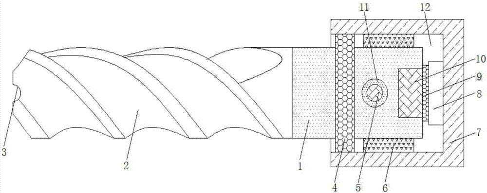
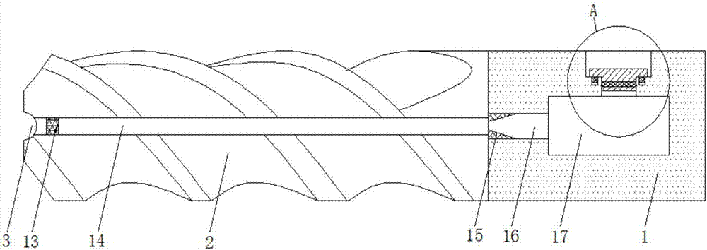
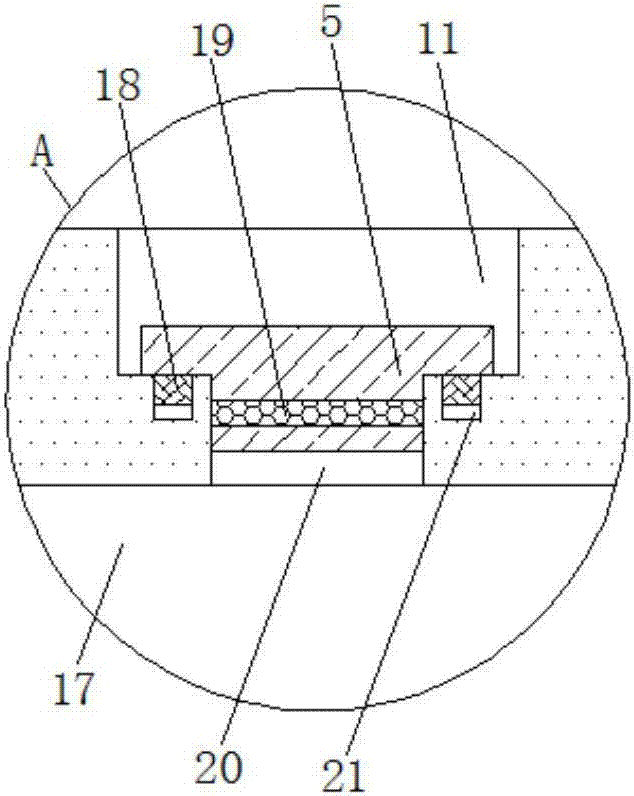
[0028] see Figure 1-3 , the present invention provides a technical solution: a high-temperature alloy end mill, including a milling cutter shaft 1 and a milling cutter head 7, the left side of the milling cutter shaft 1 is fixedly connected with a milling blade 2, and the outer teeth of the milling blade 2 are The inclination angle of the blade is one of -3° and -2°, the inclination angle of the inner tooth edge of the milling insert 2 is one of 2° and 3°, an...


PUM

PropertyMeasurementUnit
diameteraaaaaaaaaa
diameteraaaaaaaaaa
angleaaaaaaaaaa

Abstract

The invention discloses a high-temperature alloy end mill. The high-temperature alloy end mill comprises a mill bar and a mill head; a mill blade is fixedly connected to the left side surface of the mill bar; a notch is formed in the middle of the left end of the mill blade; a first drainage channel is formed in the middle of the mill blade; the notch communicates with the first drainage channel; a dustproof net is fixedly connected to the inner part of the left end of the first drainage channel; and a circular groove is formed in the outer side surface of the right end of the mill bar. According to the high-temperature alloy end mill, in the working state, lubricating fluid can flow out of the notch, and therefore the lubricating effect can be achieved, too fast abrasion of the end mill can be effectively avoided, the certain cooling performance can be achieved, the deformation of the end mill can be effectively avoided, the anti-wear effect can be good, the high-temperature-resistant performance can be high, impurities can be effectively blocked, blockage of the first drainage channel can be avoided, the leakage of liquid in a liquid storage cavity ican be avoided, the use can be more convenient, and the normal use of the end mill can be effectively guaranteed.

Description

technical field [0001] The invention relates to the technical field of end mills, in particular to a high-temperature alloy end mill. Background technique [0002] The main cutting edge of the end mill is on the cylindrical surface, and the cutting edge on the end face is a secondary cutting edge. When the end mill without a center edge is working, it cannot be fed along the axial direction of the milling cutter. There are many shapes of milling cutters. , Grooves and linear profiles processed by ordinary milling machines and CNC milling machines, and cavities processed on milling and boring machining centers. For core, surface shape or contour, two common materials for milling cutters are high-speed steel and cemented carbide. Carbide has high hardness and strong cutting force, which can increase the speed and feed rate, but the cost is high. It is easy to break the blade under the condition of rapid change of force. [0003] When the existing end mill is working, it will...

Claims


Application Information

Patent Timeline
Patent Type & Authority Applications(China)
IPC IPC(8): B23C5/10B23C5/28
CPCB23C5/10B23C5/28
Inventor 唐健陈涛
Owner 江苏扬碟钻石工具有限公司
Learn More