
While-drilling gas cut simulated experimental device and experimental method

A technology for simulating experimental equipment and gas intrusion, which is applied in the direction of buildings, etc., can solve the problems of many false alarms, the sonic signal of the sonic gas intrusion monitoring method is easily interfered, and the alarm is delayed.

Active Publication Date: 2017-08-18
BC P INC CHINA NAT PETROLEUM CORP +1
View PDF13 Cites 9 Cited by
  • Summary
  • Abstract
  • Description
  • Claims
  • Application Information

AI Technical Summary

Problems solved by technology

The surface monitoring method is characterized by easy operation, but the mud pool liquid level increment method needs the mud invaded by gas to reach the ground before detection can be carried out, which has the problem of alarm lag. The drilling fluid flow monitoring method is limited by the measurement accuracy of the sensor and the complexity of the on-site working conditions. Limitations, there are many false positives, and the sonic air intrusion monitoring method has the problem of judgment distortion because the sonic signal is easily disturbed and the processing is complicated
Downhole gas invasion monitoring tools currently use formation testing while drilling, downhole micro-flow measurement, downhole temperature measurement and other technologies to identify gas invasion. These technologies rely on indirect parameter changes caused by gas invasion for identification. Alarms are triggered when abnormalities, downhole temperature abnormalities, and drilling fluid flow rates are abnormal, and there are also problems such as many false alarms and difficult calculation of overflow volume

Method used


Image

  • While-drilling gas cut simulated experimental device and experimental method
  • While-drilling gas cut simulated experimental device and experimental method
  • While-drilling gas cut simulated experimental device and experimental method

Examples


Embodiment Construction

[0024] In order to enable those skilled in the art to better understand the technical solutions in the present application, the technical solutions in the embodiments of the present application will be clearly and completely described below in conjunction with the drawings in the embodiments of the present application. Obviously, the described The implementations are only some of the implementations of the present application, not all of them. Based on the implementation manners in this application, all other implementation manners obtained by persons of ordinary skill in the art without making creative efforts shall fall within the scope of protection of this application.

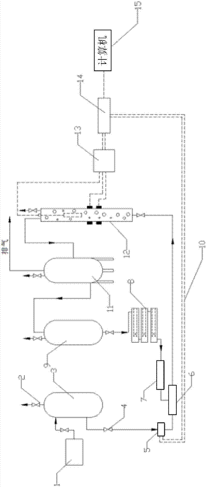
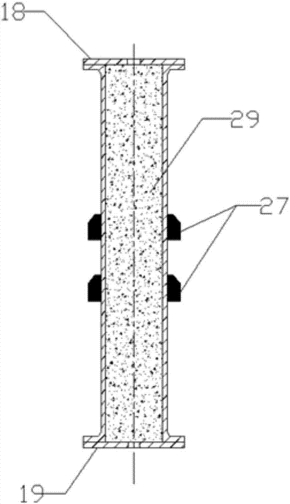
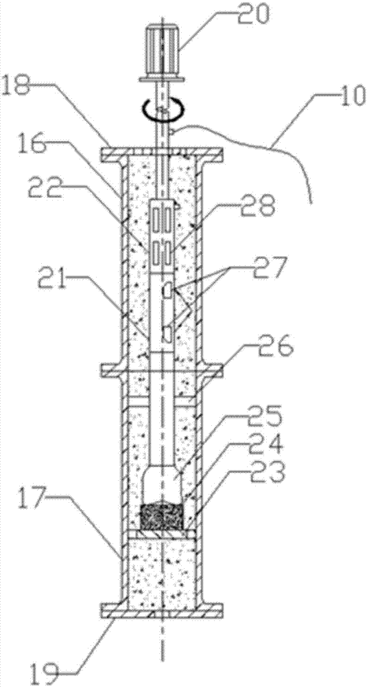
[0025] The present application provides a gas invasion simulation experiment device while drilling, and the device includes a gas-liquid delivery mechanism, a wellbore simulation experiment mechanism and a data processing mechanism. see Figure 1 to Figure 3 ,in:

[0026] The gas-liquid conveying mechani...


PUM


Abstract

The application mode of execution discloses a while-drilling gas cut simulated experimental device and an experimental method. The device comprises a gas-liquid conveying mechanism, a shaft simulated experimental mechanism and a data processing mechanism. The gas-liquid conveying mechanism comprises a gas-liquid mixer, a gas branch road and a mud branch road, wherein the gas branch road and the mud branch road are connected with the gas-liquid mixer, the gas branch road comprises a gas compressor and a gas storage tank which are mutually connected in sequence, and the gas storage tank is connected with the gas-liquid mixer; the mud branch road comprises a mud tank, a heater and a plunger pump which are mutually connected in sequence, and the plunger pump is connected with the gas-liquid mixer; the shaft simulated experimental mechanism comprises a Doppler ultrasonic theory experimental section and an underground overflow simulated test section; and the data processing mechanism comprises a front-end amplifier, a modulus collector and a computer which are connected in sequence, and the front-end amplifier is connected with the shaft simulated experimental mechanism. The technical scheme of the while-drilling gas cut simulated experimental device and the experimental method can provide data support for detecting gas cut precisely and timely.

Description

technical field [0001] The present application relates to the technical field of oil and gas exploration, in particular to a gas invasion simulation experiment device and an experiment method while drilling. Background technique [0002] In the process of oil and gas exploration and development, blowout accidents may occur during drilling, oil testing, gas testing, and oil and gas production. Blowout accidents often lead to fires, explosions, environmental pollution, casualties, equipment damage, oil and gas reservoir damage, etc. The occurrence of serious damage, prevention and control of blowout is the first priority in the safety work of oil and gas field exploration and development. [0003] Overflow is the harbinger of blowout, and the direct cause of overflow is formation fluid (oil, gas, water) intruding into the wellbore, among which gas invasion is the most harmful. When overflow occurs, if timely detection and reasonable treatment measures are taken, the occurrenc...

Claims


Application Information

Patent Timeline
IPC IPC(8): E21B47/107
CPCE21B47/107
Inventor 罗方伟孙文勇牛蕴胡家顺王增年梁爽赵永涛刘文才李默松吴祚祥李佳宜
Owner BC P INC CHINA NAT PETROLEUM CORP
Learn More