
Linear flow low noise liquid pump

A low-noise, liquid pump technology, applied in the direction of liquid fuel engines, pumps, pump components, etc., can solve the problems of large liquid output pressure fluctuations, fluctuating output liquid pressure, high plunger pump pressure, etc., to achieve uniform output pressure, tube The road is smooth and the sealing effect is good

Inactive Publication Date: 2017-08-18
袁廷华
View PDF5 Cites 2 Cited by
  • Summary
  • Abstract
  • Description
  • Claims
  • Application Information

AI Technical Summary

Problems solved by technology

The advantages of gear pumps are simple structure and low cost, but its disadvantages are large liquid output pressure fluctuations, low volumetric efficiency, and short life; vane pumps have low noise and small output liquid pressure fluctuations, but their structures are complex and require high oil quality. High; the plunger pump has high pressure and high input speed, and its disadvantages are high noise, complex structure, and fluctuations in output liquid pressure

Method used


Image

  • Linear flow low noise liquid pump
  • Linear flow low noise liquid pump
  • Linear flow low noise liquid pump

Examples


Embodiment 1

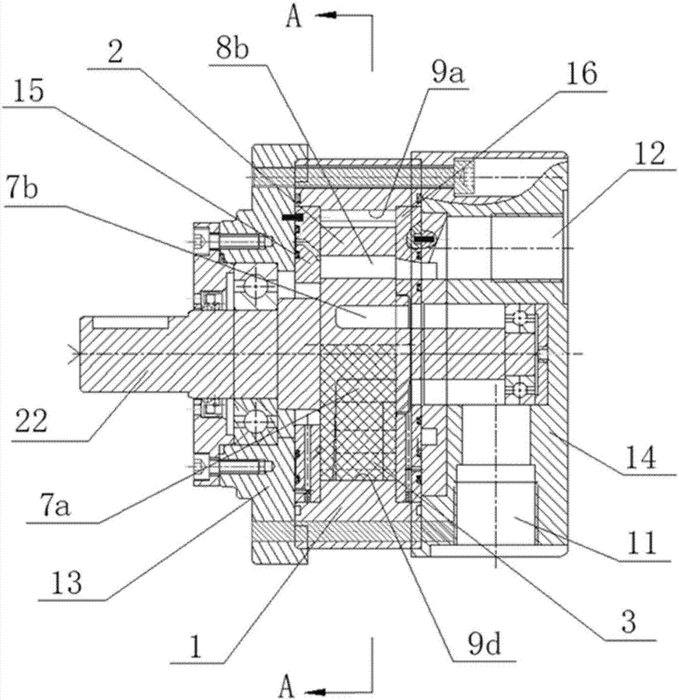
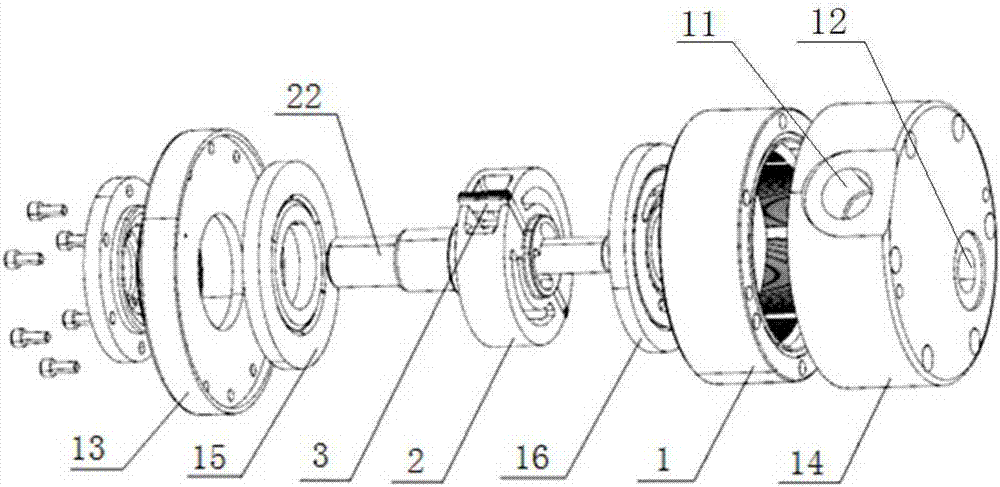
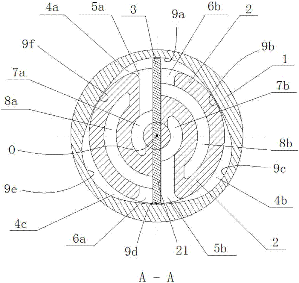
[0040] See Figure 1-Figure 5 , a linear flow low-noise liquid pump, including a casing, an input shaft 22 extending into the casing, a stator 1 fixed in the casing, a rotor 2 arranged on the inner ring of the stator 1, and blades of an integral rigid sheet structure 3. The input shaft 22 and the rotor 2 have a rigid structure or a rigid integrated structure; the wall surface of the inner ring of the stator 1 is a variable-diameter curved surface, the wall surface of the outer ring of the rotor 2 is an equal-diameter curved surface, and the inner ring of the stator 1 passes through all radial lines of the rotor center O The lengths are equal, the variable diameter surface of the inner ring of the stator 1 is divided into three equal parts, and the size and direction of each equal part are the same. Fitting, the three curved surfaces of 9a, 9c, 9e on the inner wall of the stator and the outer ring of the rotor form three isolated working cavities 4a, 4b, 4c; the rotor 2 is prov...

Embodiment 2

[0048] When the blade 3 rotates with the rotor 2, it is constrained by the variable diameter surface of the stator 1, and reciprocates in the radial direction. Taking into account the pressure of the blade 3 on the inner wall of the stator 1, the sealing effect of the blade 3 in the radial direction, and the needs of actual engineering, the following examples list several blade forms, but the protection scope of this patent is not limited to the following embodiments form.

[0049] Blade optimization 1: The blade is in the form of a master piece:

[0050] See Figure 9 , the blade includes a mother blade 31 and a daughter blade 32, the mother blade 31 is arranged in the blade groove 21, the two ends of the mother blade 31 are provided with a guide groove 33 opening toward the inner wall of the stator 1, and the daughter blade 32 is arranged in the corresponding guide groove 33 and move freely in the guide groove 33.

[0051] The thrust of the sub-blade 32 moving outwards co...

Embodiment 3

[0057] See Figure 12-Figure 16 A high-pressure chamber 8 is provided on one side of the rotor 2 facing the input shaft 22, and a low-pressure chamber 7 is provided on the other side of the rotor 2. The high-pressure chamber 8 and the low-pressure chamber 7 are separated by a separation plate 25, the liquid inlet 5 communicates with the low-pressure chamber 7, and the outlet The liquid holes 6a, 6b are connected to the cavities 8a, 8b respectively, and the liquid inlet holes 5a, 5b are respectively connected to the cavities 7a, 7b; the high-pressure balance ring 18 and the inner rotor 2 are an integrated structure or a rigid structure, and the high-pressure balance ring The function of 18 is to counteract the thrust of the high-pressure liquid through the front end cover 13 to the high-pressure chamber 8 . Among the figure, 23 is the spline shaft of the rotor 2, and 21 is the blade groove.

[0058] The working mechanism of embodiment 3 is the same as embodiment 1.


PUM


Abstract

The invention discloses a linear flow low-noise liquid pump, which comprises a casing, an input shaft extending into the casing, a stator fixed in the casing, a rotor and blades arranged on the inner ring of the stator; the wall surface of the inner ring of the stator is variable Radial curved surface, and the length of all the radial lines passing through the rotor center of the inner ring of the stator is equal; the blades are arranged in the blade slots of the rotor, and the two ends of the blades are closely attached to the wall of the inner ring of the stator; the rotor and both sides of the blades are provided with The liquid inlet hole, the liquid outlet hole, the low pressure chamber and the high pressure chamber, the inner end of the liquid inlet hole communicates with the low pressure chamber on the corresponding side of the blade, the inner end of the liquid outlet hole communicates with the high pressure chamber on the corresponding side of the blade, and the inner end of the blade on both sides The high-pressure chamber and the low-pressure chamber are isolated from each other, the low-pressure chambers on both sides of the vane are connected to the liquid inlet on the shell, and the high-pressure chambers on both sides of the blade are connected to the liquid outlet on the shell. The invention has the advantages of linear output flow and pressure, low noise, simple structure and low cost.

Description

technical field [0001] The invention relates to the field of hydraulic transmission, in particular to a liquid pump with linear flow rate and low noise. Background technique [0002] Several main types of liquid pumps on the market today include gear pumps, vane pumps, and plunger pumps. The advantages of gear pumps are simple structure and low cost, but its disadvantages are large liquid output pressure fluctuations, low volumetric efficiency, and short life; vane pumps have low noise and small output liquid pressure fluctuations, but their structures are complex and require high oil quality. High; the plunger pump has high pressure and high input speed, and its disadvantages are high noise, complex structure, and fluctuations in output liquid pressure. [0003] The reason for the high noise of the liquid pump is that in addition to the mechanical noise generated during its own operation, the main source of noise is the uneven pressure and flow of the output and input liqu...

Claims


Application Information

Patent Timeline
IPC IPC(8): F04C2/04F04C15/06F04C15/00
CPCF04C2/04F04C15/00F04C15/06
Inventor 袁廷华
Owner 袁廷华
Learn More