Novel high-end speed reducer capable of achieving lubricating oil cold and hot self-circulation effect

A self-circulating and lubricating oil technology, which is applied in gear lubrication/cooling, mechanical equipment, portable lifting devices, etc., can solve the problems of poor heat dissipation of the reducer, achieve increased strength, reduced manufacturing cost, friction coefficient wear resistance and friction reduction Effect

Pending Publication Date: 2017-08-18
四川鑫宇昌栋淮纳米科技有限公司
View PDF12 Cites 1 Cited by
  • Summary
  • Abstract
  • Description
  • Claims
  • Application Information

AI Technical Summary

Problems solved by technology

[0012] The invention provides a new type of high-end reducer with lubricating oil cold and hot self-circulation to solve the problem of poor heat dissipation of the existing reducer

Method used


Image

  • Novel high-end speed reducer capable of achieving lubricating oil cold and hot self-circulation effect
  • Novel high-end speed reducer capable of achieving lubricating oil cold and hot self-circulation effect
  • Novel high-end speed reducer capable of achieving lubricating oil cold and hot self-circulation effect

Examples


Embodiment 1

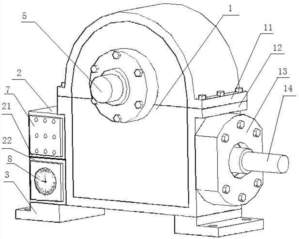
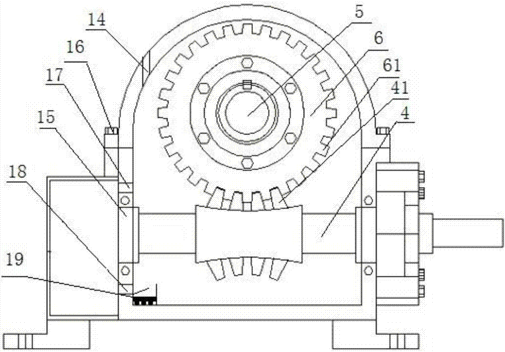
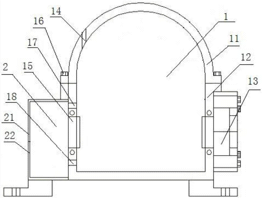
[0038] Such as Figure 1-Figure 2As shown, a new type of high-end reducer with lubricating oil cold and hot self-circulation, including an oil tank 1, a fixed orifice 3 integrated with the box body is provided under the oil tank 1, and a worm wheel 6 and a worm 4 are installed in the oil tank 1 The bearing 15 of the worm gear 6 and the worm screw 4 are meshed with each other. The oil tank 1 is filled with lubricating oil that has not passed the meshing position of the worm wheel 6 and the worm screw 4. The worm wheel 6 is connected with an output shaft 5 extending to the outside of the oil tank 1. The worm gear One end of 4 extends to the outside of the oil tank 1, and the connection between the output shaft 5, the worm 4 and the oil tank 1 is provided with a sealing cover 13 to prevent the leakage of lubricating oil, and the side of the oil tank 1 is provided with an auxiliary oil tank for self-circulation cooling and storage of lubricating oil 2. The common wall between the ...

Embodiment 2

[0042] Such as figure 2 As shown, further optimization is carried out on the basis of the new high-end reducer with lubricating oil cooling and heating self-circulation described in Example 1, so that it has the function of automatically absorbing lubricating oil residues, ensuring that the lubricating oil remains clear for a long time, and the lower oil hole 18 The bottom of the oil tank 1 below and the bottom of the fuel tank 1 on the opposite side of the lower oil hole 18 are provided with a dregs storage tank 19, and the size of the dregs storage tank 19 is 30*15*15 mm. The magnet is fixed with the dregs storage tank 19 through the insulating plate or insulating glue bonded at its bottom, and the notch of the dregs storage tank 19 is provided with a 35*10*1 mm stopper to prevent the dregs from being stored in the dregs storage tank 19. With the cold and hot self-circulation movement of the oil, it is drawn into the box again. The purpose of this embodiment is to make the ...

Embodiment 3

[0045] Further optimization is carried out on the basis of the high-end reducer described in Embodiment 1 or 2. The wall thickness of the auxiliary oil tank 2 is 5 mm. Since the oil tank 1 is used to install the worm wheel 6 and the worm 4, it will carry the weight of the worm wheel 6 and the worm 4. And the impact force brought by high-speed rotation, in order to ensure sufficient strength, the thickness of fuel tank 1 must reach more than 20mm, and the auxiliary fuel tank 2 does not need to bear the weight of worm gear 6 and worm 4 and the impact force brought by high-speed rotation, so the auxiliary fuel tank 2 The strength requirements can be appropriately reduced, and the wall thickness of the auxiliary fuel tank 2 can be reduced to 1 / 5-1 / 4 of the wall thickness of the tank. This method can not only save manufacturing costs, but the key is that due to the thinner wall thickness, its heat dissipation performance will be greatly improved. Increase.


PUM

PropertyMeasurementUnit
thicknessaaaaaaaaaa
particle sizeaaaaaaaaaa

Abstract

The invention discloses a novel high-end speed reducer capable of achieving the lubricating oil cold and hot self-circulation effect, and relates to the field of worm-gear speed reducer manufacturing. The novel high-end speed reducer comprises an oil tank, a worm gear and a worm, wherein the worm gear and the worm are engaged with each other. Bearings used for installing the worm gear and the worm are arranged inside the oil tank. The worm gear is connected with an output shaft extending to the outside of the oil tank. An auxiliary oil tank used for lubricating oil self-circulation cooling and storing is arranged by the side of the oil tank. An upper oil hole and a lower oil hole used for achieving the lubricating oil cold and hot self-circulation effect are formed in a common wall between the oil tank and the auxiliary oil tank. According to the novel high-end speed reducer, a single-oil-tank structure is changed into a double-oil-tank structure with the oil tank and the auxiliary oil tank, the oil tank serves as a heart part of the speed reducer, the auxiliary oil tank is used for assisting the oil tank in achieving lubricating oil cold and hot self-circulation so that heat can be carried away or emitted out, lubricating oil cold and hot self-circulation auxiliary heat dissipation is realized, and the problem that an existing speed reducer is poor in heat dispersion is solved.

Description

technical field [0001] The invention relates to the field of worm gear reducer manufacturing, in particular to a new type of high-end reducer with lubricating oil cooling and heating self-circulation. Background technique [0002] The reducer plays the role of matching deceleration and transmitting torque between the prime mover and the working machine or the actuator. The reducer is a relatively precise machine. The purpose of using it is to reduce the speed and increase the torque. According to the transmission type, the reducer can be divided into It is a gear reducer, a worm gear reducer and a planetary gear reducer. Among them, the worm gear reducer can be seen in various mechanical transmission systems, from military and civilian ships, automobiles, locomotives, submarines, From heavy-duty machinery and tools used in construction, processing machine tools and automatic production equipment used in the machinery industry, to common household appliances, clocks and watch...

Claims


Application Information

Patent Timeline
Patent Type & Authority Applications(China)
IPC IPC(8): F16H57/04F16H1/16F16H57/039F16H57/032F16H55/22F16H55/06
CPCF16H55/06F16H55/22F16H57/032F16H57/039F16H57/0413F16H57/0416
Inventor 邓才松张永生许红英陈蓉邓鸿月
Owner 四川鑫宇昌栋淮纳米科技有限公司
Why Eureka
Try Eureka