Self-cooling injection burner

An ejector burner and self-cooling technology, applied in burners, gas fuel burners, combustion methods, etc., can solve the problems of limited service life, high cost, and large environmental radiation, reducing radiation and increasing cooling. Effect

Pending Publication Date: 2017-08-18
SHENZHEN WISDOM ENERGY TECH CO
View PDF0 Cites 4 Cited by
  • Summary
  • Abstract
  • Description
  • Claims
  • Application Information

AI Technical Summary

Problems solved by technology

The burner head works in a high temperature environment for a long time, which will cause the material of the burner head to be resistant to high temperature. Even the high temperature resistant material has a limited service life, most of which have env

Method used


Image

  • Self-cooling injection burner
  • Self-cooling injection burner
  • Self-cooling injection burner

Examples


Example Embodiment

[0022] Before describing the embodiments in detail, it should be understood that the present invention is not limited to the detailed structure or arrangement of elements described below or in the drawings in this application. The present invention may be an embodiment implemented in other ways. Moreover, it should be understood that the terms and terms used herein are only for descriptive purposes and should not be interpreted in a limited manner. The words "include", "include", "have" and other similar words used herein mean to include the items listed thereafter, their equivalents and other additional items. In particular, when describing "a certain element", the present invention does not limit the number of the element to one, and multiple elements may also be included.

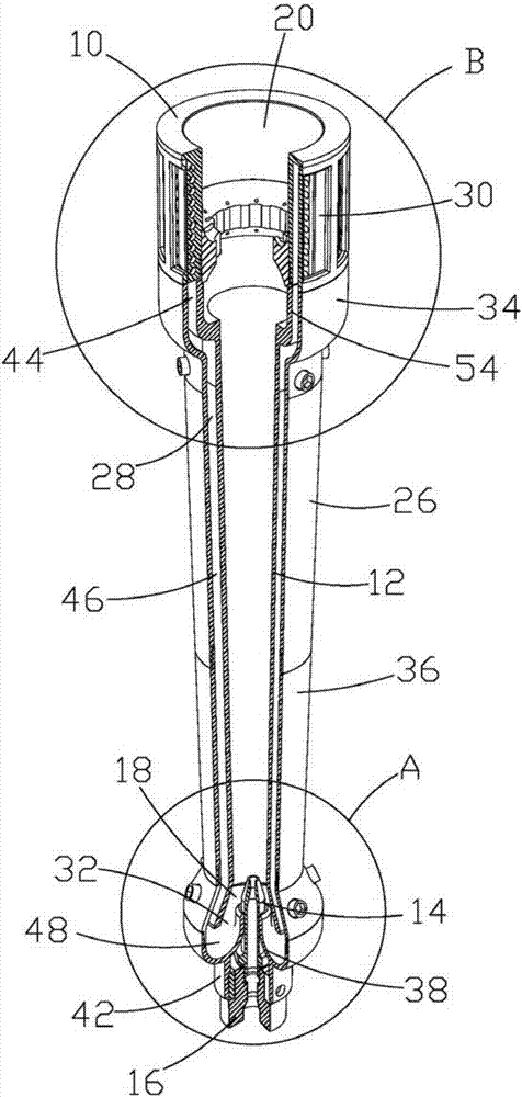
[0023] Such as figure 1 As shown, the present invention proposes a self-cooling jet combustor, which includes a combustion head 10, a mixing tube 12, a nozzle 14 and a combustor base 16. The mixing pipe 1...


PUM


Abstract

The invention provides a self-cooling injection burner. The self-cooling injection burner comprises a mixing tube, a combustion head and a nozzle. The mixing tube is provided with an air inlet end and an air outlet end. The nozzle is arranged at the air inlet end and used for spraying fuel into the mixing tube and further sucking external air into the mixing tube under the injection action. The combustion head is arranged at the air outlet end and used for combusting a mixture of the fuel and the air. The injection burner further comprises an air flow channel guiding the sucked-in air to flow. The air flow channel extends to the air inlet end of the mixing tube from the periphery of the combustion head, so that the combustion head is cooled before the sucked-in air arrives at the air inlet end of the mixing tube. Due to the fact that the air used for combustion supporting is led into the combustion head to be used for combustion supporting again after cooling, the advantages of the injection burner are reserved, and meanwhile the cooling effect of the combustion head is improved; and combustion stability is improved, the service life of the combustion head is prolonged, and radiation to the environment by the combustion head is reduced.

Description

technical field [0001] The invention relates to an ejector burner, in particular to a self-cooling ejector burner. Background technique [0002] At present, the waste gas produced in the process of oil and gas extraction is difficult to recover, and now it is mostly discharged to high-altitude flares or ground flares for combustion treatment. The existing ejector burner is a burner that does not need additional power to provide air. The air required for combustion of the ejector burner comes from the air ejected by the kinetic energy of the gas, and the injected air is directly mixed with the fuel gas. The burner head works in a high temperature environment for a long time, which will cause the material of the burner head to be resistant to high temperature. Even the high temperature resistant material has a limited service life, and most of them have environmental protection problems, and the cost is very high. And the combustion head of this kind of burner has no cooling ...

Claims


Application Information

Patent Timeline
IPC IPC(8): F23D14/04F23D14/64F23D14/78
CPCF23D14/04F23D14/64F23D14/78Y02E20/30
Inventor 胡秀文张诗明刘稼瑾
Owner SHENZHEN WISDOM ENERGY TECH CO
Why Eureka
Try Eureka