Polishing device with cooling function

A polishing device and function technology, applied in the field of polishing machines, can solve the problems affecting the chemical reaction of the polishing liquid, the thermal deformation of the workpiece, and the polishing quality of the wafer, so as to reduce the problem of uneven heat dissipation, reduce the chemical reaction, and increase the cooling force. Effect

Active Publication Date: 2022-05-13
BEIJING SEMICORE PRECISION MICROELECTRONICS EQUIP CO LTD
View PDF9 Cites 0 Cited by
  • Summary
  • Abstract
  • Description
  • Claims
  • Application Information

AI Technical Summary

Problems solved by technology

[0003] During the polishing process, the polishing disc and the driving motor that drives the polishing disc will generate a lot of heat; on the one hand, the heat will cause thermal deformation of the workpiece, which will affect the polishing quality of the wafer; on the other hand, the heat will affect the polishing liquid to a certain extent. Chemical reaction, which affects the polishing effect of the wafer, so cooling measures must be taken to control the temperature of the polishing disc

Method used


Image

  • Polishing device with cooling function
  • Polishing device with cooling function
  • Polishing device with cooling function

Examples


Embodiment Construction

[0033] The technical solutions of the present invention will be clearly and completely described below in conjunction with the accompanying drawings. Apparently, the described embodiments are some of the embodiments of the present invention, but not all of them. Based on the embodiments of the present invention, all other embodiments obtained by persons of ordinary skill in the art without making creative efforts belong to the protection scope of the present invention.

[0034] In the description of the present invention, it should be noted that the terms "center", "upper", "lower", "left", "right", "vertical", "horizontal", "inner", "outer" etc. The indicated orientation or positional relationship is based on the orientation or positional relationship shown in the drawings, and is only for the convenience of describing the present invention and simplifying the description, rather than indicating or implying that the referred device or element must have a specific orientation, ...


PUM


Abstract

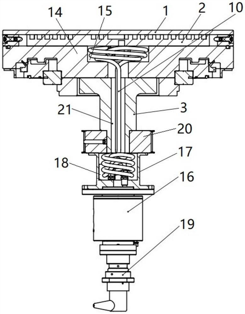
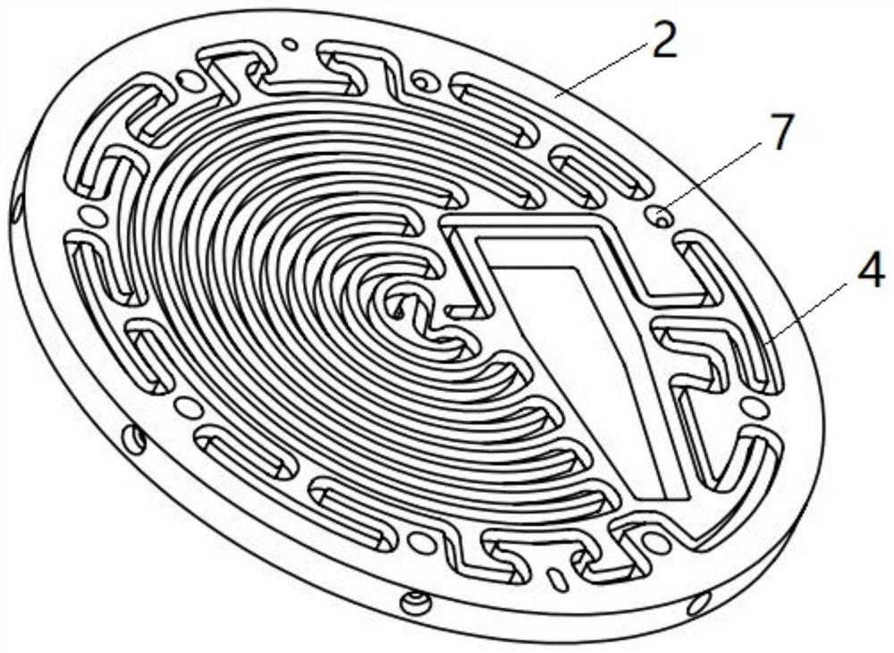
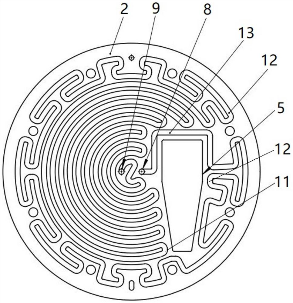
According to the polishing device with the cooling function, a polishing disc is provided with a first disc body and a second disc body which are connected in an up-down attached mode, and an avoiding hole for a sensor to penetrate through is formed in the second disc body; the rotating shaft is connected to the second disc body and used for driving the polishing disc to rotate. The cooling loop is spirally coiled between the first disc body and the second disc body, and cooling liquid can circulate in the cooling loop; a liquid inlet/return port of the cooling loop is communicated with a hose, and the hose penetrates through the shaft penetrating hole of the rotating shaft and then is suitable for being communicated with a cooling liquid tank; the avoiding hole is lapped by the cooling loop, and cooling liquid firstly flows through the cooling loop lapped in the circumferential direction of the avoiding hole; the driving assembly is at least partially arranged on the rotating shaft and used for driving the rotating shaft to rotate. According to the cooling loop, the polishing disc can be circularly cooled, and the influence of heat on the chemical reaction of the polishing liquid is reduced; and the avoiding hole is wrapped by the cooling loop, so that the sensor can be fully cooled, and the problem of non-uniform heat dissipation caused by installation of the sensor is reduced.

Description

technical field [0001] The invention relates to the technical field of polishing machines, in particular to a polishing device with a cooling function. Background technique [0002] In the field of chemical mechanical polishing technology, the wafer is clamped at the lower end of the rotating polishing head, the upper end of the rotating polishing disc is provided with a polishing pad, and a polishing liquid is provided between the wafer on the polishing head and the polishing pad. Under the action, the wafer achieves global planarization. [0003] During the polishing process, the polishing disc and the driving motor that drives the polishing disc will generate a lot of heat; on the one hand, the heat will cause thermal deformation of the workpiece, which will affect the polishing quality of the wafer; on the other hand, the heat will affect the polishing liquid to a certain extent. The chemical reaction will affect the polishing effect of the wafer, so cooling measures mu...

Claims


Application Information

Patent Timeline
Patent Type & Authority Applications(China)
IPC IPC(8): B24B37/10B24B37/12B24B37/34B24B55/02B24B41/04B24B49/00
CPCB24B37/10B24B37/12B24B37/34B24B55/02B24B41/04B24B49/00Y02P70/10
Inventor 周博伦刘福强李伟史霄
Owner BEIJING SEMICORE PRECISION MICROELECTRONICS EQUIP CO LTD
Why Eureka
Try Eureka