A Fiber Bundle Coupler with Automatic Focus Positioning

An autofocus and coupler technology, applied in the optical field, can solve the problems of decreased positioning accuracy, increased system cost, and high system complexity, and achieve the effects of avoiding eccentricity and tilt, improving reliability, and reducing errors

Active Publication Date: 2019-11-05
JINGWEI SHIDA MEDICAL TECH WUHAN CO LTD
View PDF6 Cites 0 Cited by
  • Summary
  • Abstract
  • Description
  • Claims
  • Application Information

AI Technical Summary

Problems solved by technology

[0004] (1) There is hard friction between the optical fiber connector socket and the plug, and the connection accuracy is guaranteed by mechanical precision. After being worn, the positioning accuracy will decrease;
[0005] (2) The coupling objective lens is separated from the connector socket, and an additional mechanical device must be relied on to ensure their relative positioning, and the system complexity is high;
[0006] (3) During the rotation of the locking wheel of the optical fiber connector, the spring will be subjected to lateral force, which will easily cause the locking wheel to be stuck, and the reliability is not high;
[0008] The requirement is very high, which increases the system cost

Method used


Image

  • A Fiber Bundle Coupler with Automatic Focus Positioning
  • A Fiber Bundle Coupler with Automatic Focus Positioning
  • A Fiber Bundle Coupler with Automatic Focus Positioning

Examples


Embodiment 1

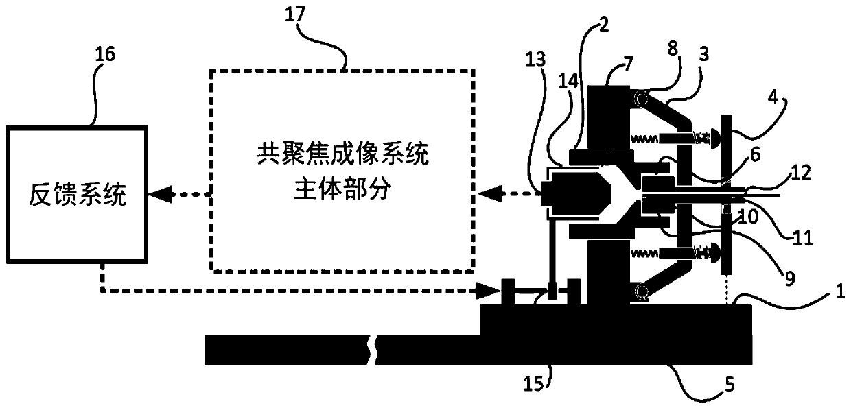
[0044]图1所示为光纤束耦合器整体结构示意图。

[0045]光纤束耦合器包括耦合器插座、耦合器插头、物镜座、对焦装置、反馈系统共5个主要部分;

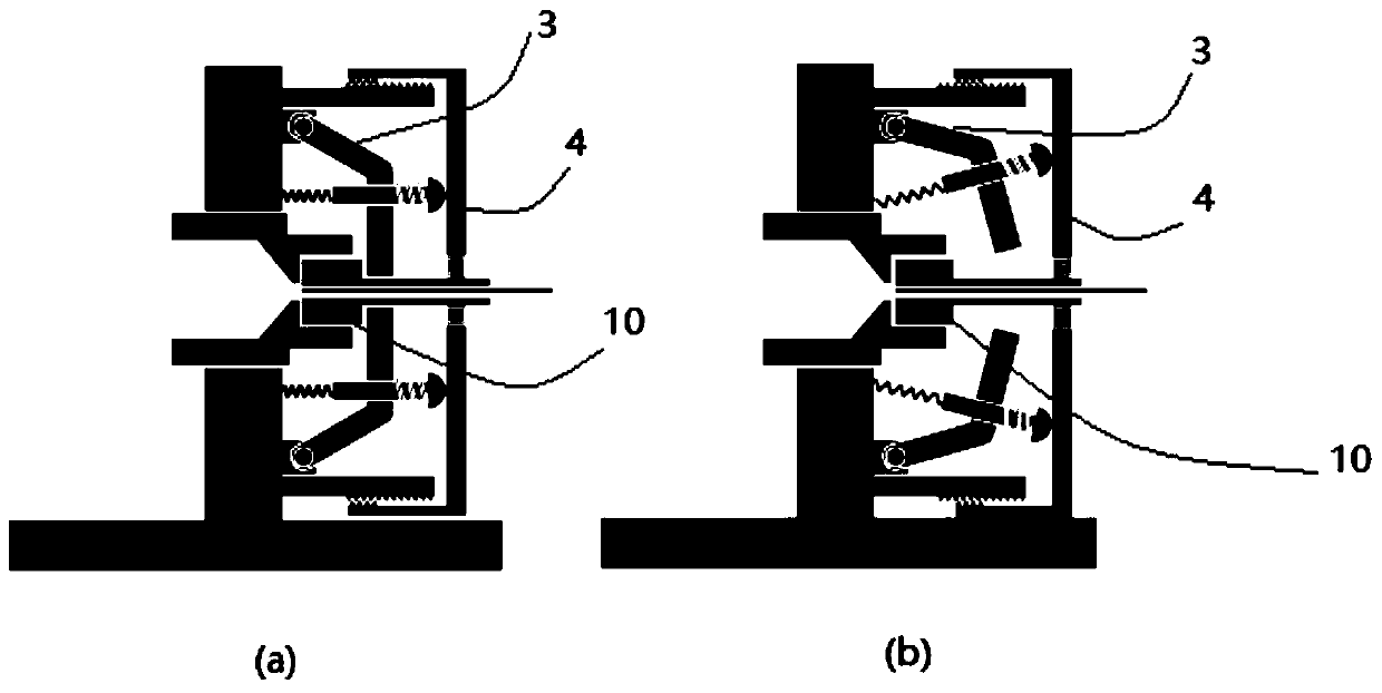
[0046]耦合器插座主要包括基座1、连接套2、压臂3、压盘4,耦合器插座基座1与共聚焦成像系统的光学底板5刚性固定;连接套与基座刚性连接,保证其与光学底板平行,连接套前端有插头定位槽6,后端有物镜滑槽7;4条压臂通过销轴8与基座连接,在连接套2周围均匀分布,可沿销轴8旋转,旋转时压臂3可压紧耦合器插头9;压盘4中央有孔洞,可容许耦合器插头9穿过,压盘4与基座1连接,使得压盘4可以沿插头定位槽方向运动,压盘4向压臂3方向运动时会压紧4条压臂3,带动压臂3压紧耦合器插头9。

[0047]耦合器插头头部有定位头10,定位头与耦合器插座上的插头定位槽形状一致;耦合器插头的轴心有空心孔洞11,光纤束12可从空心孔洞中穿过,与耦合器插头前端调节平齐后固定。

[0048]耦合物镜13刚性装配到物镜座14上,物镜座14可沿连接套后端的物镜滑槽前后运动,在移动到适当位置时,实现与耦合器插头轴心光纤束12的精确耦合。

[0049]对焦装置15安装在基座1与物镜座14之间,可推动物镜座14沿连接套后端的物镜滑槽进行运动,其中对焦装置15可以采用步进电机、伺服电机、音圈电机、压电陶瓷驱动器等精密驱动设备,其移动的步长均可小于1微米,部分设备精度可达到纳米级。对焦装置15带有专用驱动电路板,可通过外部数字信号控制其精确运动的步长,达到推动耦合物镜13进行轴向精确移动,从而实现对焦的目的。

[0050]反馈系统16为共聚焦成像系统软件的一部分。光纤束耦合器获得的光学信号进入共聚焦成像系统主体部分17,反馈系统16通过对主体部分获取的图像进行分析,判断耦合物镜13与光纤束12端面的相对位置关系。耦合物镜13的前端存在一最佳观察平面,该平面是垂直于耦合物镜光轴、直径1~2mm的一个平面。光纤束端面必须与此位置重合,轴向位置误差不超过±5微米,才能清晰成像,否则就会出现图像部分范围或全部范围的模糊。反馈系统会对获取的图像进行分析,对于耦合物镜移动的不同位置,分析其图像锐度的差异,找到锐度最高的位置,即为耦合物镜的最佳位置,此时光纤束端面所有的纤芯都位于上述"最佳观察平面”轴向±5微米范围内,从而通过对焦装置15推动物镜座14进行运动,直至找到耦合物镜13的最...

Embodiment 2

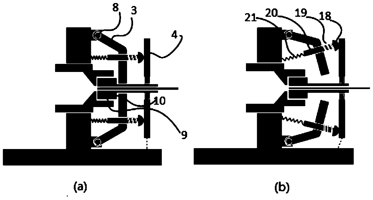
[0059]如图3(a)(b)中所示,是按照本发明中的光纤束耦合器压臂部分锁紧动作其中一种实施方式二的结构示意图,在这种实施方式中,其它的结构与实施例一中的结构完全相同,不同的是在基座1与压盖4之间设置螺纹结构,压盖4可沿着螺纹进行旋转,旋转时实现向左或向右的运动,从而带动压臂3运动,实现对定位头10的锁紧与释放。

[0060]本实施例使用螺纹实现压盖4的运动,带动压臂压紧定位头或者释放定位头,最大的益处在于,通过螺纹的传递,使得操作者在操作压盖4时,花费的力量减小,由此使得操作更为轻巧,为用户使用带来便利。

Embodiment 3

[0062]图4(a)(b)中所示,是按照本发明中的光纤束耦合器压臂部分锁紧动作其中一种实施方式三的结构示意图,在在这种实施方式中,其它的结构与实施例一中的结构完全相同,不同的是在基座1的上方设置锁紧机构,压盖4与基座1之间设置旋转轴,压盖4可以沿着旋转轴运动,在压盖4松开的过程中,复位弹簧21推动压臂3,将压臂3进行释放。

[0063]本实施例中,压盖4的下端固定,操作者在操作时,推动压盖4的上端实施锁紧。此实施例的益处在于,压盖4上端运动的距离很短,不需要旋转很大的行程才能达到压紧的效果。为用户带来另一方面的便利。在实际使用中,需要考虑运动行程与所花费作用力的关系来考虑具体的选型方案。


PUM


Abstract

The invention discloses a fiber optics bundle coupler capable of automatically focusing positioning, and the coupler comprises a coupler socket which is used for fixing a coupler plug, and is provided with a positioning head which cooperates with a plug positioning groove on the coupler socket. The coupler plug accommodates a fiber optics bundle, and the coupler socket is provided with an objective lens chute corresponding to the plug positioning groove. A coupling objective lens is controlled to slide on the objective lens chute, receives a signal from the fiber optics bundle, and transmits the signal to a confocal imaging system. The relative position relation of the coupling objective lens and the section of the fiber optics bundle is judged, and the feedback control of the sliding of the coupling objective lens is carried out till the optimal coupling position is found, thereby achieving the automatic focusing positioning. The coupler provided by the invention improves the reliability of imaging coupling, and can achieve the compensation for the device wear caused by long-time use to a certain degree.

Description

technical field [0001] The invention belongs to the field of optical technology, and more specifically relates to an optical fiber bundle coupler capable of automatic focusing and precise positioning. Background technique [0002] In the fiber bundle-based confocal imaging system, the laser emits laser light, scans the end face of the fiber bundle through the laser scanning device and the coupling objective lens, and injects the laser into each fiber core of the fiber bundle after focusing. The diameter of the core is approximately 2-3um. At the other end of the fiber bundle, the injected laser light is focused on the object to be observed through the micro-objective lens, and the object to be observed emits fluorescence under the excitation of the injected laser light, and the fluorescence returns along the same path through the core of the fiber bundle, and is finally detected by the detector captured and imaged. Therefore, the precise positioning between the coupling ob...

Claims


Application Information

Patent Timeline
Patent Type & Authority Patents(China)
IPC IPC(8): G02B6/32G02B6/36
CPCG02B6/32G02B6/3624
Inventor 马骁萧冯宇万勇段西尧
Owner JINGWEI SHIDA MEDICAL TECH WUHAN CO LTD
Why Eureka
Try Eureka