Supercharge Your Innovation With Domain-Expert AI Agents!

Switch

A technology of switches and micro switches, applied in the field of switches, can solve the problems of no neutral line, etc., and achieve the effects of convenient maintenance, stable performance, and convenient replacement

Active Publication Date: 2017-08-18
NINGBO HAIBEI ELECTRICAL APPLIANCE
View PDF7 Cites 0 Cited by
  • Summary
  • Abstract
  • Description
  • Claims
  • Application Information

AI Technical Summary

Problems solved by technology

[0003] In order to solve the technical problem that there is no neutral line in some of the above scenarios, the present invention provides a switch

Method used


Image

  • Switch
  • Switch
  • Switch

Examples


Embodiment 1

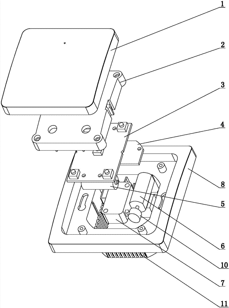
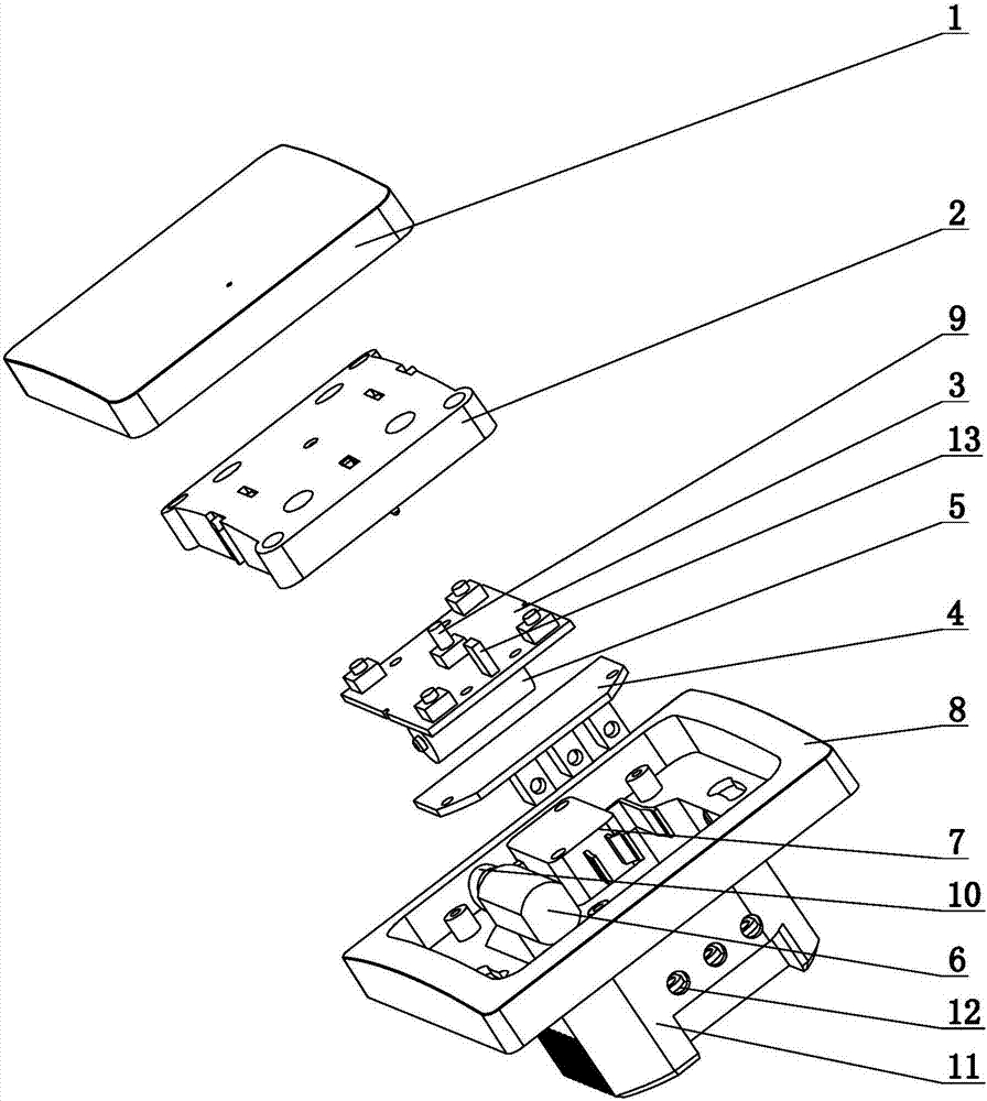
[0022] Such as figure 1 , 2 , A switch shown in 3 and 4, including a lower case 8, the surface of the lower case 8 is recessed to have an accommodating cavity, the back of the lower case 8 is provided with a housing 11, and the housing 11 is embedded in the wall during installation, so A plurality of installation holes are pierced in the accommodating chamber, and the bolts pass through the installation holes to install and fix the switch on the wall. It is connected with the micro switch 7, and drives the micro switch 7 when the driving component operates. The main control board 3 is used to receive the signal from the panel 1 and send a driving command to the driving component. The two ends of the main control board 3 are recessed inward , the corresponding position of the middle panel 2 is provided with a protrusion, which is used together to fix the main control board 3 in the middle panel 2, and the middle position of the surface of the main control board 3 is provided w...

Embodiment 2

[0030] Such as Figure 5 , 6 As mentioned above, the difference between this embodiment and Embodiment 1 is that the driving assembly includes an electromagnet 14, and the electromagnet 14 is provided with an action lever 16, and the electromagnet 14 works so that whether the action lever 16 squeezes the button 15 of the micro switch 7, The action direction of the electromagnet 14 action lever 16 is consistent with that of the micro switch 7 button 15. In the best case, the center line of the action bar 16 and the center line of the button 15 are on the same horizontal plane. 16 is released, and the button 15 of the micro switch 7 is pressed, thereby driving the micro switch 7.

Embodiment 3

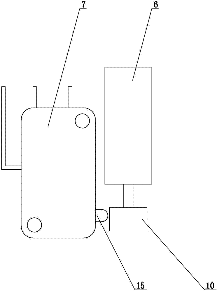
[0032] The difference between this embodiment and Embodiment 1 is that the drive assembly includes a drive motor 6 and a turntable 10, the turntable 10 is connected to the head of the drive motor 6, and the turntable 10 is provided with a depression. At the same level, the button 15 is in the recess in the initial state. When the driving motor 6 receives the driving signal, the turntable 10 rotates at a certain angle, and the rest of the turntable 10 contacts the button 15, and the button 15 is pressed to drive the microswitch 7.


PUM


Abstract

The invention relates to the field of accessories of domestic appliances, particularly to a switch. The switch comprises a lower shell, wherein an accommodating cavity is formed in the surface of the lower shell in a concave manner; a shell is arranged on the back surface of the lower shell in a convex manner; a driving part, a micro switch and a main control board are arranged in the accommodating cavity; the driving part is connected with the micro switch; a contact point is arranged in the middle position of the surface of the main control board; the contact point passes through a middle panel to be exposed outwardly and to be connected with the panel; the main control board is connected with a battery; the middle panel is fixed on the lower shell; a component connected with the micro switch is arranged in the shell; and a wiring hole used for connecting the component is formed in the shell. The switch has the beneficial effects as follows: an external alternating current power supply is not needed, and the switch is powered by a dry cell; a chip transmits an instruction, and a micro motor controls the way of the micro switch to directly control the on-off of a connected circuit, so that the purpose that a null line is not needed is achieved; and in addition, by adopting the dry cell for supplying power, stable performance, safety and durability, and convenience in replacement can be realized.

Description

technical field [0001] The invention relates to the field of household electrical appliance accessories, in particular to a switch. Background technique [0002] With the development of society and the improvement of people's living standards, the demand for intelligence is increasing, and the intelligence in the home environment is the first place to be applied and popularized. At present, when installing some switches, an external AC power supply is required to achieve control. The on-off of the connected lines, but in some scenarios, there is no neutral line, and an additional neutral line needs to be laid, which is very inconvenient to install and use, and increases the cost of wiring. There are many inconveniences, and it is very inconvenient to install an intelligent switch. Contents of the invention [0003] In order to solve the technical problem that there is no neutral line in some of the above scenarios, the present invention provides a switch. [0004] Technic...

Claims


Application Information

Patent Timeline
IPC IPC(8): H01H3/26H01H3/28H01H3/32H01H3/42
CPCH01H3/26H01H3/28H01H3/32H01H3/42
Inventor 文毅
Owner NINGBO HAIBEI ELECTRICAL APPLIANCE
Features
  • R&D
  • Intellectual Property
  • Life Sciences
  • Materials
  • Tech Scout
  • Unparalleled Data Quality
  • Higher Quality Content
  • 60% Fewer Hallucinations
Learn More