
Antenna structure and designing method thereof

A technology of antenna structure and design method, applied in the fields of radar, microwave radio frequency, and electronics, can solve the problems of large insertion loss, circuit board area, cost increase, and complicated transmitting circuit, so as to achieve the effect of simple transmitting part and reducing cost.

Active Publication Date: 2017-08-18
SOUTHEAST UNIV +1
View PDF5 Cites 15 Cited by
  • Summary
  • Abstract
  • Description
  • Claims
  • Application Information

AI Technical Summary

Problems solved by technology

[0007] For the application of radar systems with both long-range and medium-range detection, the current several technologies have related shortcomings: the use of millimeter-wave switches for switching, entering a large insertion loss, consuming precious millimeter-wave power, and the switching of the switch also brings The synchronization problem between different modes increases the complexity of the back-end algorithm
The use of phased array at the transmitting end requires the introduction of a phase shifting part, which makes the circuit of the transmitting part greatly complicated, and the area and cost of the circuit board are greatly increased.
The most important thing is that neither of the above two solutions can realize the radar system to work in the medium-range and long-range modes at the same time
The third solution is equivalent to using two sets of hardware to independently realize the function of medium and long-distance detection, which will greatly increase the cost, circuit area and complexity of baseband processing data
However, at present, there is no substrate-integrated waveguide antenna that can support the application of medium and long-distance integration of W-band speed measuring radar

Method used


Image

  • Antenna structure and designing method thereof
  • Antenna structure and designing method thereof
  • Antenna structure and designing method thereof

Examples


Embodiment Construction

[0040] Below in conjunction with accompanying drawing, the present invention is described in further detail:

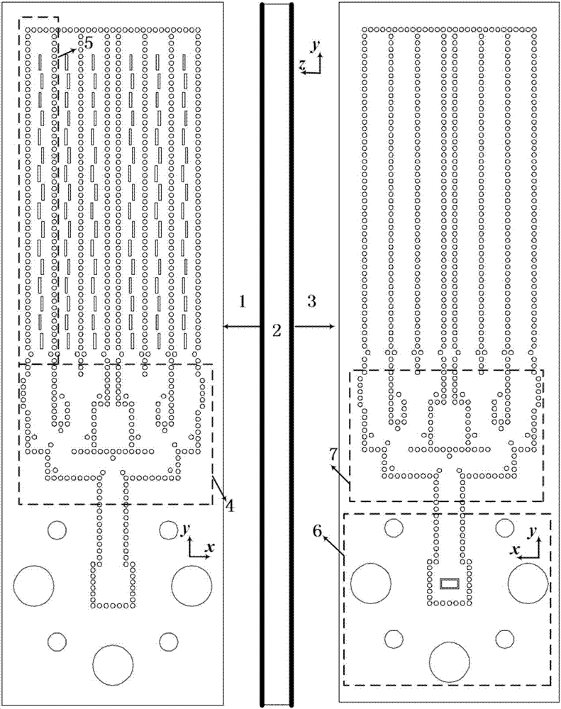
[0041] Such as figure 1 As shown, the antenna array structure involved in the present invention includes an upper metal structure 1 , a dielectric substrate 2 and a lower metal structure 3 . The antenna array structure includes a SIW linear array radiating unit 5 , a feeding network 4 (7 is a rear view of the feeding network) and a SIW-to-standard rectangular waveguide 6 . The substrate-integrated waveguide power divider of the feeding network 4 has a structure in which one channel is divided into 2N channels, and N is an integer greater than or equal to 3. In this embodiment, N takes a value of 3. The antenna array has a total of 6 linear array radiation elements along the +x direction, which together form an overall antenna array. All circular holes in the figure represent metallized through holes. The linear array radiation unit 5 is in the form of a substrate i...


PUM


Abstract

The invention discloses an antenna structure and a designing method thereof, wherein the antenna structure comprises a line array radiating unit and an electric feeding network. The electric feeding network has an axis symmetric structure. The electric feeding network comprises an equal-power and unequal-power substrate integrated waveguide power divider and a substrate integrated waveguide phase shifter. The radiating unit is connected with the end of the axis symmetry substrate integrated waveguide feeding network. The antenna of the invention realizes a middle-and-long-distance integrated antenna based on the substrate integrated waveguide structure. The antenna can simultaneously satisfy requirements for testing the middle distance and the long distance of a radar, and switching between a plurality of transmitting antennae by means of a switch is not required. Furthermore the antenna structure has advantages of compact structure, low cost, small dimension, etc.

Description

technical field [0001] The invention relates to the fields of electronics, microwave radio frequency, radar and the like, and in particular relates to a structure and a design method of a novel array antenna. [0002] technical background [0003] status quo [0004] Millimeter-wave antenna arrays are widely used in radar, navigation, satellite communication, indoor high-speed communication and other occasions due to their excellent performance such as compactness and high gain. [0005] As a key component of the radar system, the antenna has a very important impact on the link index performance of the entire system. There are three main types of ranging radars: long-range, medium-range, and short-range. According to the radar equation: detection of farther targets requires greater equivalent isotropic radiated power (EIRP), and blindly increasing the transmit power is impractical, so the longer the detection distance, the higher the antenna array gain required. Long-range...

Claims


Application Information

Patent Timeline
IPC IPC(8): H01Q13/20H01Q21/00H01Q21/06
CPCH01Q13/20H01Q21/0037H01Q21/0087H01Q21/061
Inventor 洪伟余英瑞张慧
Owner SOUTHEAST UNIV
Learn More