Waste treatment process for a fossil-fuel extraction site

A technology for waste treatment and fossil fuels, applied in mining wastewater treatment, chemical instruments and methods, mining fluids, etc., can solve problems such as high cost and difficulty

Inactive Publication Date: 2017-08-18
DPS BRISTOL HOLDINGS LTD
View PDF5 Cites 1 Cited by
  • Summary
  • Abstract
  • Description
  • Claims
  • Application Information

AI Technical Summary

Problems solved by technology

[0005] Fossil fuel extraction stations are often located in remote parts of the wor

Method used


Image

  • Waste treatment process for a fossil-fuel extraction site
  • Waste treatment process for a fossil-fuel extraction site

Examples


Embodiment Construction

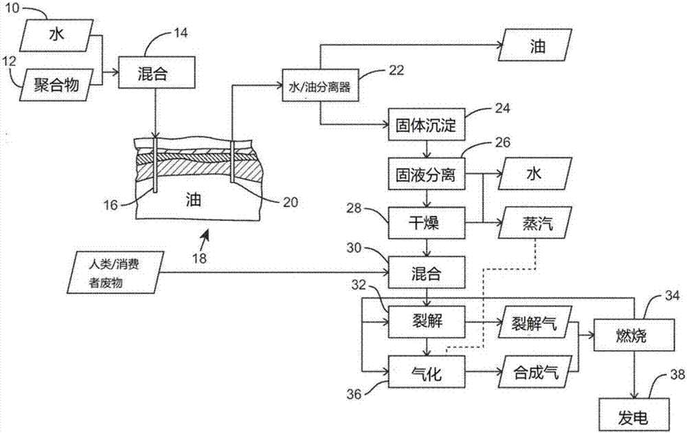
[0026] figure 1 Shown is the enhanced oil recovery (EOR) polymer flooding process for Field 18 and the waste treatment process of the present invention for treating produced water and oil from EOR.

[0027] In a polymer flooding process, water from a water source 10 and polymer from a polymer source 12 are mixed in a mixing step 14 and injected into an oil reservoir in an oil field 18 via an injection well 16 . The polymer is selected from polymers with long chain macromolecules, which when mixed with water form a high viscosity solution. In the illustrated embodiment, the polymer is polyacrylamide "PAM" (or hydrolyzable polyacrylamide HMPA), but in other embodiments any suitable material may be chosen. In a typical enhanced oil recovery (EOR) process, the polymeric material is present in solution at 5-10% by weight.

[0028] The lower end of the injection well 16 is located in the oil reservoir of the oil field 18, so that the solution of water and polymer injected into the...


PUM


Abstract

There is disclosed a waste treatment process for a fossil-fuel extraction site (18, 40), comprising: processing extracted waste generated by a fossil-fuel extraction process to produce primary waste having a higher calorific value than the extracted waste; mixing the primary waste with secondary waste to generate pyrolysis feedstock, the secondary waste having a lower calorific value than the primary waste; pyrolysing the pyrolysis feedstock in a pyrolysis unit (32) to form pyrolysis char; and gasifying the pyrolysis char in a gasification unit (36) to form syngas and ash.

Description

technical field [0001] The present invention relates to a waste treatment method for a fossil fuel mining station. Background technique [0002] Fossil fuel extraction stations, such as oil wells and drilling sites for oil, gas, and other fossil fuel exploration, are often located on land or offshore in remote locations. Additionally, oil exploration will continue in challenging and remote regions such as the Arctic and Antarctic. [0003] In addition to the extraction of fossil fuels, the extraction of some fossil fuels generates waste streams, at least a portion of which contain materials of high calorific value. For example, the drilling process requires drilling fluid to flush and keep drilling cuttings in suspension in the wellbore. Common drilling fluids include oil-based drilling fluids (OBMs) based on petroleum products (such as diesel) and synthetic oil-based drilling fluids (SBMs) based on synthetic oils. Drilling fluid and drilling cuttings are by-products that...

Claims


Application Information

Patent Timeline
IPC IPC(8): C10J3/66E21B41/00E21B43/22E21B43/36E21B21/06
CPCC10J3/66E21B21/066E21B41/005E21B43/16E21B43/36Y02P20/145C10J2300/0909C10J2300/0903C10J2300/0926C10B53/00C10J3/00C10J3/58E21B21/06E21B43/35C02F1/463C02F1/66C02F2103/10C10B57/04C10B57/10C10J2300/0906C10J2300/094C10J2300/1643E21B21/063E21B21/068E21B43/20
Inventor 大卫·约翰·帕金森尼克·卢克·帕尔默
Owner DPS BRISTOL HOLDINGS LTD
Why Eureka
Try Eureka