
Angular speed measuring method and device based on photoelectric oscillator

A photoelectric oscillator and measuring device technology, applied in the directions of measuring devices, instruments, surveying and navigation, etc., can solve problems such as affecting the performance of the measuring system, being difficult to achieve, affecting the measuring accuracy, etc., and achieving the effect of improving the sensitivity and resolution

Active Publication Date: 2017-08-22
BEIJING JIAOTONG UNIV
View PDF5 Cites 16 Cited by
  • Summary
  • Abstract
  • Description
  • Claims
  • Application Information

AI Technical Summary

Problems solved by technology

But this method requires a highly coherent light source, which is difficult to achieve in practice
In addition, the line width of the resonator oscillation frequency will affect the improvement of measurement accuracy, so a high-quality oscillation signal is required, and the line width of the light wave signal generated by the current fiber resonator is difficult to meet the needs of high-precision measurement of angular velocity
[0009] In addition, when optical equipment (such as optical spectrum analyzer) is used for measurement, the performance of the measurement system is affected due to the low resolution and low response speed of the optical equipment.

Method used


Image

  • Angular speed measuring method and device based on photoelectric oscillator
  • Angular speed measuring method and device based on photoelectric oscillator
  • Angular speed measuring method and device based on photoelectric oscillator

Examples


Embodiment Construction

[0038] Embodiments of the present invention are described in detail below, examples of which are shown in the drawings, wherein the same or similar reference numerals denote the same or similar elements or elements having the same or similar functions throughout. The embodiments described below by referring to the figures are exemplary only for explaining the present invention and should not be construed as limiting the present invention.

[0039]Those skilled in the art will understand that unless otherwise stated, the singular forms "a", "an", "said" and "the" used herein may also include plural forms. It should be further understood that the word "comprising" used in the description of the present invention refers to the presence of said features, integers, steps, operations, elements and / or components, but does not exclude the presence or addition of one or more other features, Integers, steps, operations, elements, components, and / or groups thereof. It will be understood...


PUM


Abstract

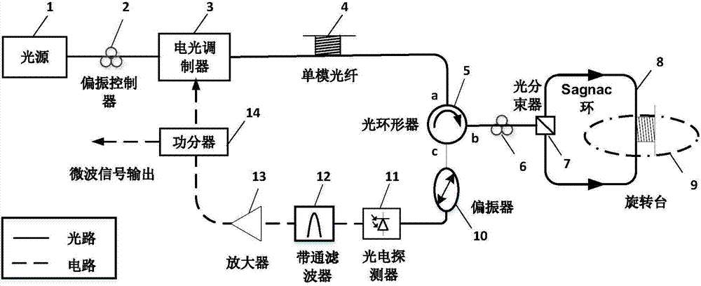
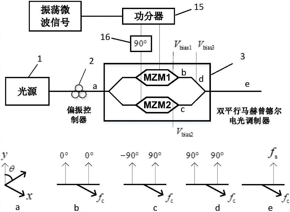
The invention provides an angular speed measuring method and device based on a photoelectric oscillator. The device comprises a light source, a first polarization controller, an electrooptical modulator, an Sagnac interferometer, a photoelectric detector, a band filter, a microwave amplifier and a power divider, wherein the Sagnac interferometer comprises an optical circulator, a second polarization controller, a light beam splitter, a Sagnac ring, a rotating table and a polarizer. The method comprises the steps: measuring the frequency fosc of an oscillator signal output by the powder divider when the Sagnac ring is static, measuring the frequency f'osc of an oscillator signal output by the powder divider when the Sagnac ring rotates at the angular speed omega, and calculating the angular speed omega based on the fosc, the f'osc and the parameters of the loop circuit of the photoelectric oscillator. According to the angular speed measuring method and device based on the photoelectric oscillator, the Sagnac ring is embedded into the photoelectric oscillator, the phase change of the Sagnac ring resulted from the angular speed omega is mapped to the oscillation frequency change of the photoelectric oscillator, and simultaneously, the advantages of high-quality microwave signals produced by the photoelectric oscillator and high-resolution microwave measurement are combined, thereby greatly improving the sensitivity and resolution in measuring the angular speed omega.

Description

technical field [0001] The invention relates to the technical field of angular velocity measurement, in particular to a photoelectric oscillator-based angular velocity measurement method and device. Background technique [0002] Angular velocity measurement technology plays a huge role in the fields of military, navigation and aviation, communication, industry and civil navigation, and many methods and devices for measuring angular velocity have been developed. The first device used to measure angular velocity is a mechanical gyroscope, which uses a high-speed rotating moving body, which is not only costly, difficult to maintain, but also has a short service life. In the early 20th century, the discovery of the Sagnac effect laid a theoretical foundation for the development of optical gyroscopes. At that time, the development of optical fiber technology was still immature, and people used ring laser cavity to measure angular velocity. This technical method does not need mov...

Claims


Application Information

Patent Timeline
IPC IPC(8): G01C19/66
CPCG01C19/661
Inventor 王目光张静
Owner BEIJING JIAOTONG UNIV
Learn More