Equipment and method for detecting thermoelectric performance parameters of one-dimensional micro/nanomaterials
A technology of thermoelectric properties and electrical parameters, which is applied in the thermal development of materials, measurement of electricity, and measurement of electrical variables, etc.
- Summary
- Abstract
- Description
- Claims
- Application Information
AI Technical Summary
Problems solved by technology
Method used
Image

Examples
Embodiment 1
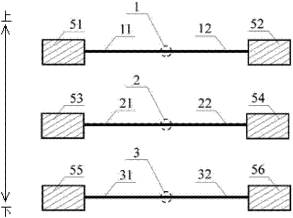
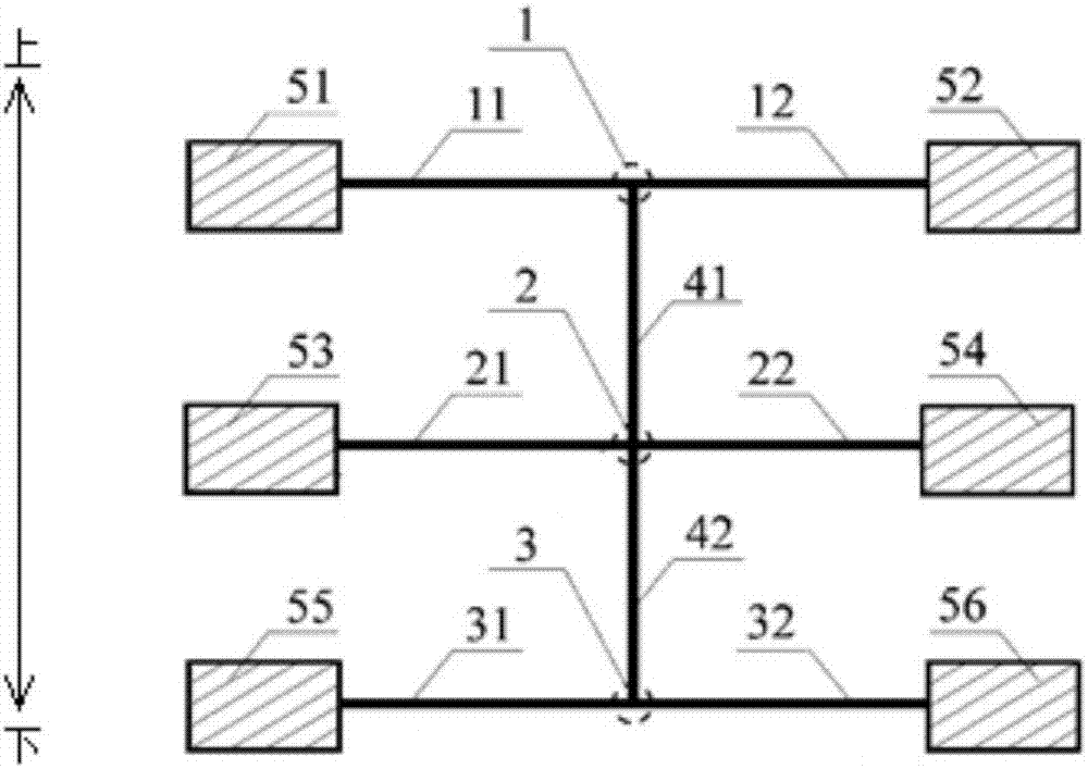
[0149] In this example, using figure 1 the detection device shown, and follow the figure 2 The sample to be tested is connected by the lap joint method, and the thermoelectric performance parameters of the sample to be tested are detected.
[0150] specific, figure 1 In the detection device shown, the three test lines are overlapped by parallel suspensions, and their end points are respectively connected to heat sink 51, heat sink 52, heat sink 53, heat sink 54, heat sink 55 and heat sink 56, and the sample to be tested is The suspension in the vertical direction is lapped on the test line, respectively connected to the heating line at lap point 1, connected to the first induction line at lap point 2, connected to the second induction line at lap point 3, and lap point 1 , lap point 2 and lap point 3 divide the test line and the sample to be tested into test line 11, test line 12, test line 21, test line 22, test line 31, test line 32, the upper section of the sample to be ...
PUM
 Abstract
Description
Claims
Application Information
PatSnap Eureka turns technology decisions into work you can execute. Powered by our Innovation Knowledge Graph, it runs expert workflows across engineering, life sciences, materials and intellectual property. Get your review-ready output in minutes.


