Photoelectric frequency response tester and test method thereof

A test method and tester technology, applied in the field of optoelectronics, can solve the problems of inability to test optical-electrical conversion devices, insufficient spectral test resolution, poor flexibility and reliability, etc., to facilitate integration and packaging, improve measurement accuracy and flexibility. performance and reliability, wide frequency range

Active Publication Date: 2017-08-22
UNIV OF ELECTRONICS SCI & TECH OF CHINA
View PDF8 Cites 18 Cited by
  • Summary
  • Abstract
  • Description
  • Claims
  • Application Information

AI Technical Summary

Problems solved by technology

[0004] The object of the present invention is: in the test of above-mentioned electro-optic and photoelectric conversion device, existing method only is aimed at the test of single device, single frequency response parameter, the testing resolution of spectroscopic method is insufficient and photoelectric conversion device can't be tested, The frequency sweep method cannot get rid of the influence of other auxiliary devices on the measurement of the device under test, and additional calibration is required, resulting in the problems of high measurement cost, low measurement accuracy, and poor flexibility and reliability. The present invention provides a high-precision, wide-bandwidth photoelectric frequency Response tester to realize self-calibration test of multiple devices and various frequency response parameters

Method used


Image

  • Photoelectric frequency response tester and test method thereof
  • Photoelectric frequency response tester and test method thereof
  • Photoelectric frequency response tester and test method thereof

Examples


Embodiment

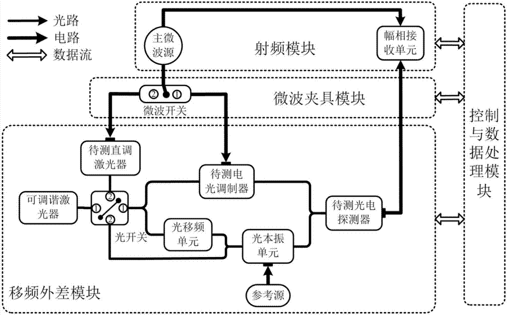
[0094] The wavelength λ of the laser output optical carrier 0 =1552.36nm, the optical frequency shifting unit uses an acousto-optic frequency shifter with a frequency shift of 70MHz, the electro-optic modulator to be tested is an electro-optic intensity modulator, and the optical local oscillator unit is an electro-optic intensity modulator.

[0095] Close the optical switch and microwave switch at 1 port:

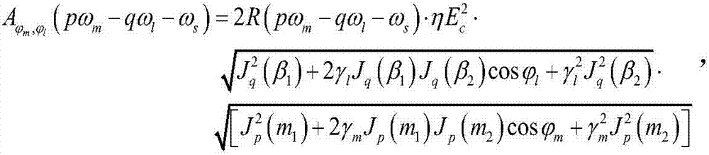
[0096] Set the frequency of the sinusoidal microwave signal output by the main microwave source to 7.52 GHz, and the frequency of the sinusoidal microwave signal output by the reference source to 7.5 GHz. After the optical signal output by the Mach-Zehnder interferometer is photoelectrically detected, the frequency measured by the amplitude-phase receiving unit is 0.09 GHz(ω m -ω l +ω s ), 15.09GHz (ω m +ω l +ω s ) amplitude values, respectively According to formula (5), it can be obtained that the photodetector to be tested has a frequency of 15.09GHz (ω m +ω l ...


PUM


Abstract

The invention relates to a photoelectric frequency response tester and a test method thereof. The photoelectric frequency response tester is composed of a frequency shift heterodyne module, a microwave clamp module, a radio frequency module and a control and data processing module. The frequency shift heterodyne module is composed of a directly modulated laser to be tested, a tunable laser, an optical switch, an electro-optic modulator to be tested, an optical frequency shift unit, an optical local oscillation unit, a reference source and a photoelectric detector to be tested. The microwave clamp module provides a microwave switch and different radio frequency port use scenes. The radio frequency module is composed of a main microwave source and an amplitude phase receiving unit. The optical switch and the microwave switch are controlled, the frequency relation of the sinusoidal microwave signals outputted by the main microwave source and the reference source is set, and the required spectrum sideband is analyzed through cooperation of the amplitude phase receiving unit so that the frequency response characteristic parameters of the directly modulated laser to be tested, the electro-optic modulator to be tested and the photoelectric detector to be tested can be acquired, additional calibration test of the conventional method can be eliminated, the test cost of the photoelectronic device can be reduced, and the test accuracy and the flexibility and the reliability of the device can be enhanced.

Description

technical field [0001] The invention belongs to the measurement technology of frequency response characteristic parameters of optoelectronic devices in the technical field of optoelectronics, and in particular relates to a photoelectric frequency response tester and a test method. Background technique [0002] With the rapid increase of communication rate and bandwidth, traditional electronic devices can no longer meet the needs of modern optical communication network transmission, and optoelectronic devices with high speed and wide bandwidth have become the main components of optical fiber communication systems, while direct modulation lasers, electro-optical modulation When optical devices and photodetectors are converted between electricity and light or light and electricity in optical fiber communication systems, their modulation coefficient, half-wave voltage, amplitude / phase-frequency response, and chirp parameters gradually deteriorate with the increase of frequency, w...

Claims


Application Information

Patent Timeline
Patent Type & Authority Applications(China)
IPC IPC(8): G01R23/14
CPCG01R23/14
Inventor 张尚剑王恒刘俊伟邹新海姬在文张雅丽刘永
Owner UNIV OF ELECTRONICS SCI & TECH OF CHINA
Why Eureka
Try Eureka