Voltage resisting type isolation transformer box of traction substation

An isolation transformer, traction substation technology, applied in distribution substations, substation/switch layout details, emergency protection circuit devices for limiting overcurrent/overvoltage, etc., can solve the damage of DC power equipment, control and protect equipment and DC power supply equipment damage, insulation breakdown and other problems, to achieve the effect of eliminating overvoltage

Pending Publication Date: 2017-08-22
四川艾德瑞电气有限公司
View PDF9 Cites 2 Cited by
  • Summary
  • Abstract
  • Description
  • Claims
  • Application Information

AI Technical Summary

Problems solved by technology

[0004] Affected by the working mode of the existing traction substation where the low-voltage power distribution cabinet directly provides working power to the electric isolating switch, in actual work, when a power frequency short circuit occurs in the catenary power supply system, the power frequency short circuit current will flow along the catenary power supply system If the pillar is grounded, a very high power frequency counter-attack overvoltage is formed on the pillar grounding body, the pillar, and the shell of the operating mechanism box of the electric isolating switch. The overvoltage is easily ungrounded from the shell of the operating mechanism box of the electric isolating switch The discharge of the low-voltage cable line caused insulation breakdown, and then the low-voltage cable introduced the overvoltage into the low-voltage distribution cabinet, causing damage to the equipment in the low-voltage distribution cabinet, and may further cause control in the traction substation connected to the low-voltage distribution cabinet. Protection against damage to equipment and DC power supplies
[0005] In another case, during operation, when lightning strikes the wires of the catenary power supply system, a traveling wave overvoltage will be generated on the wires. into the ground along the pillars of the catenary power supply system; or after the lightning strikes the pillars of the catenary power supply system, the lightning current will also enter the ground along the pillars of the catenary power supply system; A very high lightning strike back overvoltage is formed on the shell of the operating mechanism box of the electric isolating switch, and the overvoltage is likely to be discharged from the shell of the operating mechanism box of the electric isolating switch to the low-voltage cable line inside the shell, causing insulation breakdown, and then , Low-voltage cables introduce overvoltage into the low-voltage power distribution cabinet, causing damage to the equipment in the low-voltage power distribution cabinet, and may further cause damage to the control and protection equipment and DC power supply equipment in the traction substation connected to the low-voltage power distribution cabinet
[0006] To sum up, whether it is a power frequency short circuit, a lightning strike to the wire of the catenary power supply system, or a lightning strike to the pillar of the catenary power supply system, it may cause the potential of the pillar of the catenary power supply system and its grounding body to rise, resulting in the operation of the electric isolating switch. The shell of the mechanism box discharges to the low-voltage cables inside the shell, and then causes overvoltage to be introduced into the low-voltage power distribution cabinet of the traction substation through the low-voltage cable, causing damage to the equipment in the low-voltage power distribution cabinet and the equipment connected to it. Therefore, a When such an overvoltage occurs, it is particularly necessary to effectively prevent damage to the equipment in the low-voltage power distribution cabinet of the traction substation and the equipment connected to the low-voltage power distribution cabinet.

Method used


Image

  • Voltage resisting type isolation transformer box of traction substation

Examples


Embodiment Construction

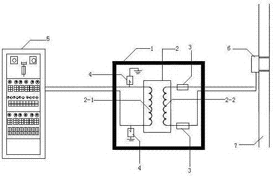
[0017] figure 1 As shown in , the voltage-resistant isolation transformer box of the traction substation is composed of a box body 1, a voltage-resistant isolation transformer 2, a fuse 3, and a surge protector 4. The fuse 3 and the surge protector 4 have the same Two of them, pressure-resistant isolation transformer 2, fuse 3, and surge protector 4 are installed in the box body 1, and the primary side 2-1 of the voltage-resistant isolation transformer is respectively connected to the low-voltage distribution of the traction substation. The two ends of the power output of the electric cabinet 5 are connected by wires, one end of the two surge protectors 4 is respectively connected to the two ends of the primary side 2-1 of the withstand voltage isolation transformer by wires, and the other ends of the two surge protectors 4 are respectively connected to the The box body 1 is connected by wires, one end of the two fuses 3 is respectively connected to the secondary side 2-2 powe...


PUM


Abstract

Provided is a voltage resisting type isolation transformer box of a traction substation. The box comprises a box body, a voltage resisting type isolation transformer, two same fuses and two same surge protectors. The voltage resisting type isolation transformer, the fuses and the surge protectors are installed in the box body. Primary-side power supply input two ends of the voltage resisting type isolation transformer are connected with power output two ends of a low-voltage power distribution cabinet of the traction substation through wires. Two ends of the surge protectors are connected with primary-side two ends of the voltage resisting type isolation transformer through wires. Other ends of the two surge protectors are connected with the box body through wires. Two ends of the two fuses are connected with auxiliary-side power supply output two ends of the voltage resisting type isolation transformer through wires, and other ends of the two fuses are connected with power supply input two ends of electrical parts in an operation mechanism box of an electric isolation switch of an electrical railway contact network power supply system. According to the invention, damage to devices in the low-voltage power distribution cabinet of the traction substation caused by overvoltage is avoided and the box has profound prospects.

Description

technical field [0001] The invention relates to the field of supporting equipment used in electrified railway traction substations, in particular to a voltage-resistant isolation transformer box for traction substations. Background technique [0002] In electrified railways, the power supply facilities of the traction substation provide power to electric locomotives and EMUs through the catenary power supply system above the railway; during operation, if the catenary power supply system above the railway fails, the power supply system will interrupt the power supply In the end, it will cause the transportation of some sections of the railway to stop, which will have a great impact on the economy and politics. In the existing technology, in order to reduce the outage time of the power supply system after the failure of the catenary power supply system, shorten the scope of the fault, and quickly restore the power supply after the failure, the power supply line of the catenary...

Claims


Application Information

Patent Timeline
Patent Type & Authority Applications(China)
IPC IPC(8): H02B1/46H02B7/06H02H9/04
CPCH02B1/46H02B7/06H02H9/047
Inventor 陈纪纲许晓蓉陈刚袁勇唐元方林宗良何宏国贺毅姚夕平尹磊李剑曹毅峰周瑶代文平王尧
Owner 四川艾德瑞电气有限公司
Why Eureka
Try Eureka