Automatic pin penetrating device for lifting hooks of gantry crane

A technology for gantry cranes and automatic pinning, which is applied in the directions of transportation, packaging, and load hanging components, etc. It can solve the problems of personal safety threats to climbing workers, cumbersome pinning operations, time-consuming and laborious operations, and unfavorable flood control work, so as to avoid climbing Easy to operate, easy to install, and reduce labor intensity

Active Publication Date: 2017-08-25
STATE GRID CORP OF CHINA +2
View PDF10 Cites 2 Cited by
  • Summary
  • Abstract
  • Description
  • Claims
  • Application Information

AI Technical Summary

Problems solved by technology

Since the threading pin is installed on the hook, the weight is heavy, and the hook is in a tilted state when it comes out. The threading work requires the cooperation of multiple workers to lift the threading pin to keep the hook in balance, and at the same time keep the hook in alignment with the balance beam. Only then can the threading operation be carried out, and the threading operation is cumbersome, time-consuming and laborious
Because the pinning operation point is high from the ground, and the edge of the adjacent dam is higher than the crest guardrail, the staff need to climb up to work, and there are great safety hazards
The pinning work of the door crane hook and the balance beam is the first step in the lifting of the spillway door. If it is blocked, it is not conducive to the development of flood control work. Generally, the door cranes at the top of the dam are in the outdoor environment, and encounter severe weather such as strong wind and heavy rain. , it also poses a great threat to the personal safety of climbing workers

Method used


Image

  • Automatic pin penetrating device for lifting hooks of gantry crane
  • Automatic pin penetrating device for lifting hooks of gantry crane
  • Automatic pin penetrating device for lifting hooks of gantry crane

Examples


Embodiment Construction

[0027] The technical solutions of the present invention will be further specifically described below through the embodiments and in conjunction with the accompanying drawings.

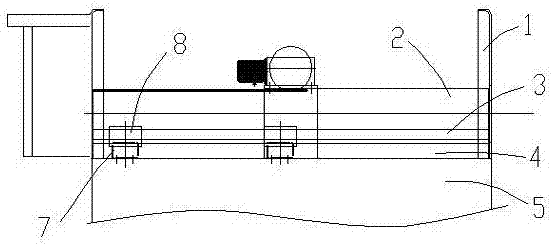
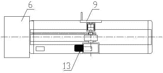
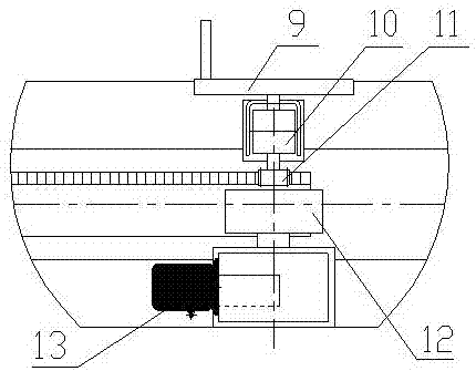
[0028] In this embodiment, an automatic pin-pinning device for the hook of a gantry crane is arranged on the balance beam 17 at the top of the spillway door 18, and includes a pin-pinning bed base 5, an electric control box 6 located at one end of the pin-pinning bed base 5, and The centering seat 14 that the door machine hook 16 cooperates in the up and down direction, such as figure 2 , Figure 4 , Figure 5 As shown, the pin-through bed base 5 is provided with two places, that is, two pin-through devices are established on a balance beam 17, and the two pin-through devices are distributed on the two ends of the balance beam 17, and each pin-through bed base 5 The outer end is equipped with a centering seat 14. The two pin-threading devices can be controlled independently or act simultaneously. ...


PUM


Abstract

The invention discloses an automatic pin penetrating device for lifting hooks of a gantry crane. The automatic pin penetrating device comprises a pin penetrating machine tool seat and a centering seat, wherein the pin penetrating machine tool seat is located on a balance beam at the top of a spillway door, and the centering seat is matched with the lifting hooks of the gantry crane. The automatic pin penetrating device is characterized in that a penetrating pin with straight line guiding mechanisms is arranged in the pin penetrating machine tool seat; a mobile transmission mechanism and a manual transmission mechanism are arranged in a manner of being matched with the penetrating pin; the mobile transmission mechanism comprises a driving device and a friction wheel matched with the penetrating pin; a mechanical locking device is arranged at the head of the penetrating pin; and a wireless receiving controller is arranged in the driving device. Through the adoption of the automatic pin penetrating device disclosed by the invention, the automation of the overall process of pin penetrating between the gantry crane and a grabbing beam is realized; the working at a high place of an operator is avoided, so that the labor intensity is greatly reduced, the safety of the pin penetrating work is guaranteed, the working efficiency is improved, and the spot space is effectively utilized; and the integral structure is simplified, so that the automatic pin penetrating device is convenient to mount, and the developing of the overhauling and maintaining work is facilitated.

Description

technical field [0001] The invention relates to reservoir flood discharge equipment technology, in particular to an automatic pin-pinning device for a gantry crane hook. Background technique [0002] The automatic threading device is widely used in engineering machinery, such as the patent announcement number is CN205187635U, a kind of automatic threading device for high-temperature material tanks, including a driving pulley block, the bottom of the driving pulley block is connected with the main body of the grabbing beam, and the lower end of the main body of the grabbing beam There are two grasping ears welded symmetrically in the face, and the grasping ears and the lifting lugs on the high-temperature material tank are connected by two symmetrically arranged automatic pin-threading devices to form a pin shaft connection. The automatic pin-threading device includes a motor, which is fixedly installed at the lower end of the main body of the grabbing beam On the heat shield...

Claims


Application Information

Patent Timeline
Patent Type & Authority Applications(China)
IPC IPC(8): B66C1/34B66C1/40B66C13/22
CPCB66C1/34B66C1/40B66C13/22
Inventor 赖江波马俊顾承庆邓亚新张帆邓金荣刘江邹祖平鲍献忠童斌尹滨崔健康
Owner STATE GRID CORP OF CHINA
Why Eureka
Try Eureka