Hybrid energy storage lifting system for engineering machinery

A hybrid energy storage and construction machinery technology, applied in the field of hydraulic systems, can solve problems such as low energy utilization, and achieve the effects of high energy storage and utilization, precise control, and high positioning accuracy

Active Publication Date: 2017-08-25
TAIYUAN UNIV OF TECH
View PDF5 Cites 7 Cited by
  • Summary
  • Abstract
  • Description
  • Claims
  • Application Information

AI Technical Summary

Problems solved by technology

[0004] In order to solve the problems existing in hybrid drive such as low energy utilization rate, the present invention provides a hybrid energy storage

Method used


Image

  • Hybrid energy storage lifting system for engineering machinery
  • Hybrid energy storage lifting system for engineering machinery
  • Hybrid energy storage lifting system for engineering machinery

Examples


Embodiment 1

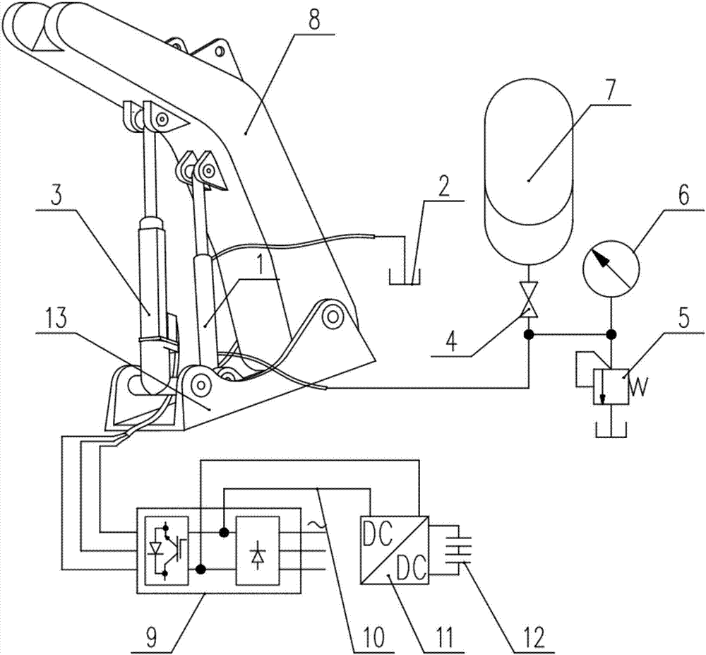
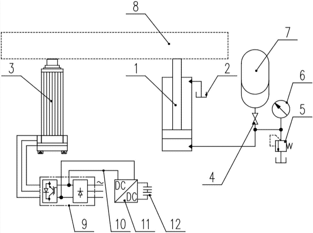
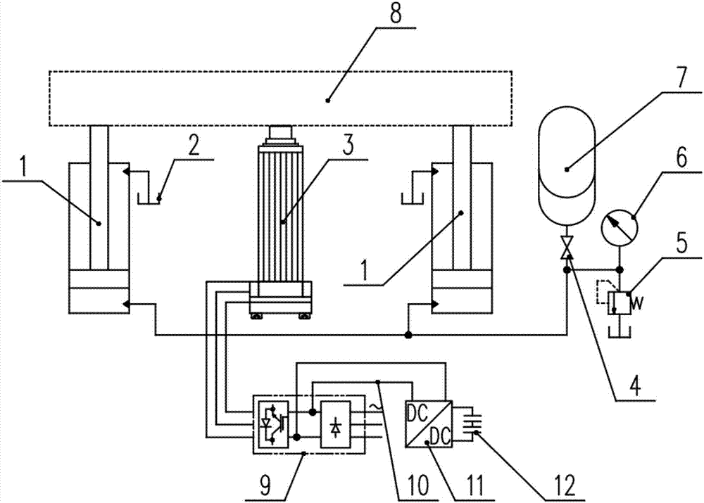
[0027] Such as Figure 3-4 As shown, the hybrid energy storage lifting system for construction machinery in this embodiment includes two liquid-pneumatic composite energy storage cylinders 1 and an electric cylinder 3; the electric cylinder 3 is arranged in the middle, and the two liquid-pneumatic composite energy storage cylinders Cylinder 1 is symmetrically arranged on both sides of the electric cylinder 3, and the piston rod ends of the two liquid-pneumatic composite energy storage cylinders 1 and 3 are hinged on the boom 8 along the center line. The cylinder block is hinged on the upper frame. The rod chamber of the liquid-gas composite energy storage cylinder 1 is connected to the fuel tank 2; the rodless chamber of the liquid-gas composite energy storage cylinder 1 is connected to one end of the shut-off valve 4, the inlet of the pressure gauge 6 and the overflow valve 5 through the pipeline, and the shut-off The other end of the valve 4 is connected with the inlet of t...

Embodiment 2

[0029] Such as Figure 5 As shown, the hybrid energy storage lifting system for construction machinery in this embodiment includes a liquid-pneumatic composite energy storage cylinder 1 and two electric cylinders 3; the liquid-pneumatic composite energy storage cylinder 1 is arranged in the middle, and the two electric Cylinder 3 is symmetrically arranged on both sides of liquid-pneumatic composite energy storage cylinder 1 . The cylinder body end of the liquid-gas composite energy storage cylinder 1 and the cylinder body ends of the two electric cylinders 3 are coaxially hinged on the upper frame 13, and the piston rod end of the liquid-gas composite energy storage cylinder 1 and the pistons of the two electric cylinders 3 The rod ends are respectively hinged on the boom 8 . The rod chamber of the liquid-gas composite energy storage cylinder 1 is connected to the fuel tank 2; the rodless chamber of the liquid-gas composite energy storage cylinder 1 is connected to one end of...


PUM


Abstract

The invention discloses a hybrid energy storage lifting system for engineering machinery. The system comprises at least one liquid and gas composite energy storing cylinder, at least one electric cylinder, a hydraulic energy accumulator, at least one frequency converter, a direct current bus, a bidirectional direct current to direct current (DC-DC) convertor, a super capacitor group, an oil tank, a stop valve, an overflow valve, a pressure gauge, an upper frame and a movable arm, wherein the electric cylinder serves as a main driving working cylinder; the gravity of the movable arm is balanced by adopting the liquid and gas composite energy storing cylinder and the hydraulic energy accumulator; and the gravitational potential energy of the movable arm is directly transformed into electric energy and hydraulic energy to be stored. The hybrid energy storage lifting system for the engineering machinery, disclosed by the invention, has the advantages of high potential energy recycling efficiency, safety, reliability, energy saving, environment protecting and the like.

Description

technical field [0001] The invention belongs to the technical field of hydraulic systems, and in particular relates to a hybrid energy storage lifting system for engineering machinery. Background technique [0002] At present, construction machinery such as excavators and loaders mostly use hydraulic systems to drive the boom, and use the boom to rise and fall to perform operations. During the working process, the boom needs to be frequently reciprocated up and down. However, for the existing boom lifting system, often due to the heavy weight of the boom itself, when the hydraulic cylinder drives it up, the hydraulic system needs to overcome its gravity to do work, which consumes a lot of energy; , The gravitational potential energy of the boom will be converted into heat energy through the throttling of the hydraulic valve, which will not only waste energy, but also increase the oil temperature of the hydraulic system, increase the failure rate of the system, and affect th...

Claims


Application Information

Patent Timeline
IPC IPC(8): B66F13/00F15B1/02F15B21/00
CPCB66F13/00F15B1/02F15B21/00
Inventor 权龙王波权仲翊夏连鹏
Owner TAIYUAN UNIV OF TECH
Why Eureka
Try Eureka