Flow rectifier and reaction cavity

A locking device and an integrated technology, applied in the direction of gaseous chemical plating, metal material coating process, coating, etc., can solve the problems of spray plate deformation and air leakage, and reduce expansion deformation and gas leakage , Solve the unsatisfactory effect of processing technology

Active Publication Date: 2017-08-25
BEIJING NAURA MICROELECTRONICS EQUIP CO LTD
View PDF4 Cites 0 Cited by
  • Summary
  • Abstract
  • Description
  • Claims
  • Application Information

AI Technical Summary

Problems solved by technology

[0007] The technical problem to be solved by the present invention is to provide a flow equalizing device and a reaction chamber to solve the problems of spray plate deformation and air leakage in the prior art in view of the above-mentioned defects in the prior art

Method used


Image

  • Flow rectifier and reaction cavity
  • Flow rectifier and reaction cavity
  • Flow rectifier and reaction cavity

Examples


Embodiment Construction

[0029] In order to enable those skilled in the art to better understand the technical solutions of the present invention, the present invention will be further described in detail below in conjunction with the accompanying drawings and embodiments.

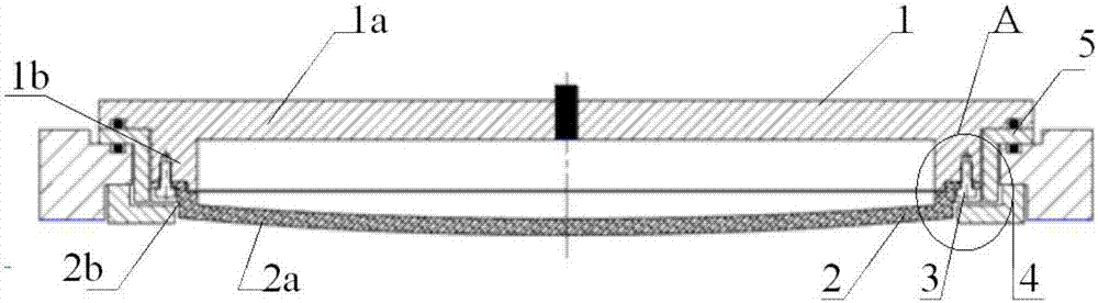
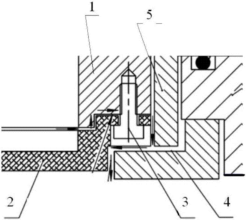
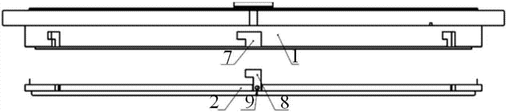
[0030] image 3 It is a schematic diagram of the connection structure of the flow equalizing device provided by the embodiment of the present invention. In order to solve the limitation of radial expansion caused by the screw connection in the prior art, this embodiment uses the outer wall of the second connection part 2b of the spray plate 2 The outer wall of the first connection part 1b of the radio frequency cover 1 is provided with engaging parts that cooperate with each other, and the radio frequency cover 1 and the spray plate 2 are fixedly connected, so that the radial expansion of the spray plate 2 is not limited, and the problem is solved. Deformation of spray disc 2.

[0031] Specifically, this embodiment adopts the way...


PUM


Abstract

The invention provides a flow rectifier. The flow rectifier comprises a radio frequency cover and a spraying plate. The radio frequency cover comprises an upper part and a lower part which are fixedly connected into a whole. The upper part of the radio frequency cover is a first disc body, and the lower part of the radio frequency cover is a first annular connecting part. The outer diameter of the first connecting pat is smaller than the diameter of the first body. The spraying plate comprises an upper part and a lower part which are fixedly connected into a whole. The upper part of the spraying plate is a second annular connecting part, and the lower part of the spraying plate is a second disc body. The outer diameter of the second connecting part is greater than the diameter of the second body. The outer side wall of the first connecting part and the outer side wall of the second connecting part are provided with matching clamping parts in the axial direction correspondingly, so that the radio frequency cover is fixedly connected with the spraying plate. Through the flow rectifier provided by the invention, the problem of non-ideal machining processes caused by gas leakage and deformation can be effectively solved, and the flow rectifier has good conduction characteristic.

Description

technical field [0001] The invention relates to the technical field of semiconductor equipment manufacturing, in particular to a flow equalizing device and a reaction chamber. Background technique [0002] Plasma-enhanced chemical vapor deposition (PECVD) equipment is mainly used to deposit and coat the surface of sapphire or silicon wafers. The reaction chamber of PECVD equipment is the place where the coating occurs, and its structure is particularly important. Many important indicators for deposition and coating are related to the chamber. The structure is closely related, such as the uniformity of gas flow, the size of the chamber, the conductivity of the chamber, etc. PECVD equipment generally uses a radio frequency cover and a spray plate to form a flow equalization device. The purpose is to make the reaction gas enter the reaction area more uniformly and deposit the film on the For the reaction on the wafer, the uniformity of the gas flow is very important, which can ...

Claims


Application Information

Patent Timeline
Patent Type & Authority Applications(China)
IPC IPC(8): C23C16/455
CPCC23C16/455
Inventor 王福来
Owner BEIJING NAURA MICROELECTRONICS EQUIP CO LTD
Why Eureka
Try Eureka