

Micro-strip quasi-Yagi antenna with directional diagram being reconfigurable in pitching plane
A quasi-yagi and directional pattern technology, applied in the directions of antenna, radiating element structure, electrical components, etc., can solve the problem of complex structure, and achieve the effect of expanding the scanning dimension and simple structure
- Summary
- Abstract
- Description
- Claims
- Application Information
AI Technical Summary
Problems solved by technology
Method used
Image

Examples
specific Embodiment approach 1
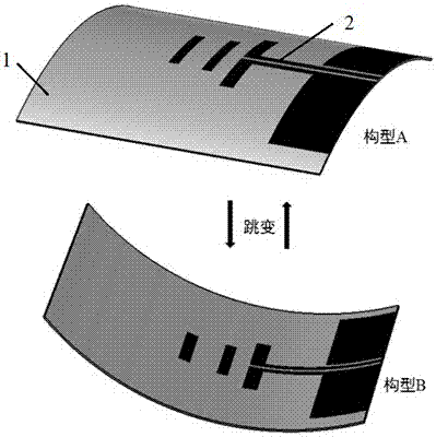
[0016] Specific Embodiment 1: The reconfigurable microstrip quasi-Yagi antenna with the in-plane direction diagram provided in this embodiment consists of a bistable composite material dielectric substrate 1 that is orthogonally laminated, and a bistable composite material dielectric substrate 1 that is laid on the upper layer of the bistable composite material dielectric substrate 1. The microstrip quasi-Yagi antenna layer 2 is composed of a jump driver laid on the lower layer of the bistable composite material dielectric substrate 1 .
[0017] In this embodiment, the microstrip quasi-Yagi antenna layer 2 and the jump driver are integrally cured and formed with the bistable composite material dielectric substrate 1 .
[0018] In this embodiment, the bistable composite material dielectric substrate 1 produces two cylindrical stable configurations after curing, and the curvature directions of the two cylindrical stable configurations are opposite, so that the pattern of the micr...
specific Embodiment approach 2
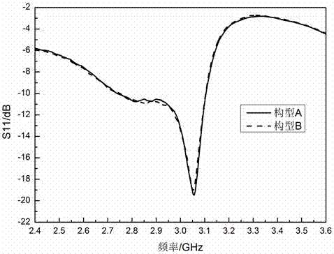
[0025] Specific implementation mode 2: In this implementation mode, a reconfigurable microstrip quasi-Yagi antenna with a working frequency of 3 GHz in the elevation plane is taken as an example for illustration.
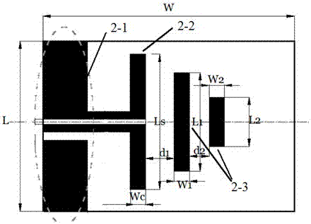
[0026] like figure 1 As shown, the reconfigurable microstrip quasi-Yagi antenna with the in-plane direction diagram of the elevation plane of this embodiment is composed of a bistable composite material dielectric substrate 1 that is orthogonally laminated, and a microstrip quasi-yagi antenna laid on the upper layer of the bistable composite material dielectric substrate 1. The Yagi antenna layer 2 is composed of a jump driver laid on the lower layer of the bistable composite material dielectric substrate 1, and all components are integrated and solidified.
[0027] In this embodiment, the bistable composite material dielectric substrate 1 is a glass fiber reinforced composite material, using [0 2 / 90 2 ]Layer method, the thickness of a single layer is 0.125mm, th...
PUM
| Property | Measurement | Unit |
|---|---|---|
| Single layer thickness | aaaaa | aaaaa |
| Center frequency | aaaaa | aaaaa |
| Bandwidth | aaaaa | aaaaa |
Abstract
Description
Claims
Application Information