Compensation device with adjustment of reactive power capacity by autotransformer

An autotransformer, compensation device technology, applied in reactive power compensation, reactive power adjustment/elimination/compensation, circuit devices, etc., to achieve the effect of increasing the voltage regulation range

Active Publication Date: 2017-08-25
POWERCHINA FUJIAN ELECTRIC POWER SURVEY & DESIGN INST CO LTD +1
View PDF5 Cites 6 Cited by
  • Summary
  • Abstract
  • Description
  • Claims
  • Application Information

AI Technical Summary

Problems solved by technology

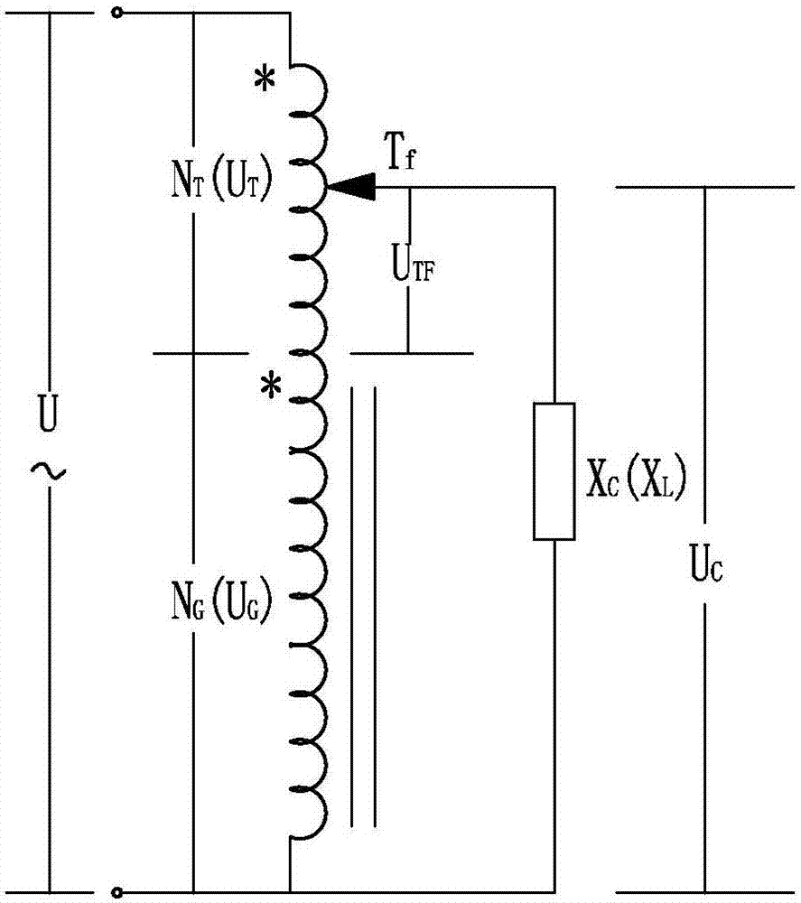
where S Be is the rated capacity of the autotransformer, which is equal to the maximum reactive power compensation capacity S M , the S Be The capacity S transmitted directly by the autotransformer circuit d And the electromagnetic capacity S transmitted by the electromagnetic induction of the autotransformer m It consists of two parts, namely S Be = S d +S m , Because the cost of the autotransformer depends on the electromagnetic capacity S m , S m The smaller the value, the better the economy, which is just opposite to the requirement of M value, for example, M=2.8, K=1.67, Take

Method used


Image

  • Compensation device with adjustment of reactive power capacity by autotransformer
  • Compensation device with adjustment of reactive power capacity by autotransformer
  • Compensation device with adjustment of reactive power capacity by autotransformer

Examples


example 1

[0091] Example 1, in a 10kV power grid, the capacitive reactive power compensation capacity Qce=10Mvar connected to the 10kV bus of the main transformer, when implemented according to M=7, the rated capacity of the autotransformer S Be =10MVA, electromagnetic capacity When the adjustment rate of up and down is the same When selecting capacitor parameters according to the national standard and industry standard, it should be greater than U De = 6.06kV capacitor rated voltage has 7.22kV, 8.4kV, at this time U Be =(1-k d )U Ce =(1+t t )U De , U Be Rated voltage U of the 10kV busbar of the main transformer for the autotransformer De Decrease the maximum voltage of the voltage output, and get: take k d =0.05, U Ce =7.22kV, then t t =0.132; take k d =0.05, U Ce =8.4kV, then t t = 0.317. choose t t =0.317, by Available: t x = 0.502.

[0092] by N X = t x ×N G According to the position of the selected tap changer K Tf Calculate the number of turns of each vo...

example 2

[0111] Example 2: When the capacitive reactive capacity Qce=20Mvar connected to the 10kV bus of the main transformer, for M=7, 2 auto-on-load capacity-adjusting transformers should be selected, and the M=3.5 of each auto-transformer, t=0.303, U Be =(1-k d )U Ce =(1+t t )U De , Similarly, take k d =0.05, U De =6.06kV, U Ce =8.4kV,t t = 0.317. Desirable t x = t t = 0.31. Depend on m -1 =0.236S Be , select the number of positions K of the tap changer Tf =12, the number of adjustable gears is 2*22 gears, △q m = 2.15%, A ∑TK =2[10+9+(0.236 2.5+1)25]=1.175 million yuan;

[0112] There are four groups of fixed groups, and their capacities are 3Mvar, 6Mvar, 6Mvar, and 6Mvar respectively, so their investment costs are:

[0113] A ∑G =A KG +A C =4 10+2 29=980,000 yuan

[0114] The investment cost of the existing auto-capacitance adjustment scheme is:

[0115] A ∑T =[10+14+(1+0.47×2.5)×25]×2=1.568 million yuan, the number of adjustable gears is 2×17=34 gears. ...

example 3

[0116] Example 3: When the capacitive reactive capacity Qce=3×10Mvar connected to the 10kV bus of the main transformer, M ∑ =7, 3 autocapacity regulating transformers should be selected, M=M of each autotransformer ∑ / 3=2.33, t=0.209, take k d =0.05, U Ce =7.22kV,t t =0.132, take t t =0.15, then t x =0.25, m -1 =0.173, select the position number K of the tap changer Tf = 12, K X =11,K t =7,

[0117] A ∑TK =3×[10+9+(1+0.173×2.5)×25]=1.644 million yuan, 54 adjustable gears.

[0118] There are four groups of fixed groups, and their capacities are 4.2Mvar, 8.4Mvar, 8.4Mvar, 8.4Mvar, Q ∑ =29.4Mvar, so its investment cost is:

[0119] A ∑G =4 10+3 29=1.27 million yuan

[0120] The investment cost of the existing auto-capacitance adjustment scheme is:

[0121] A ∑T =3×[10+14+(1+0.346×2.5)×25]=2.119 million yuan, the number of adjustable gears is 3×17=51 gears.


PUM


Abstract

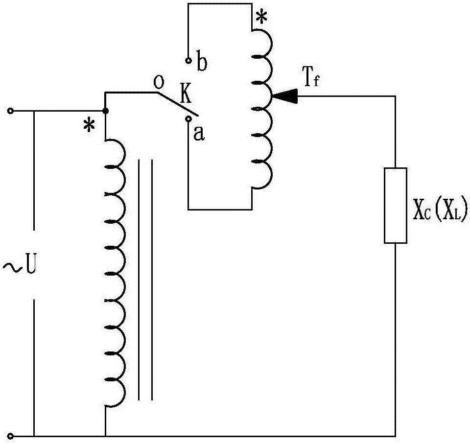
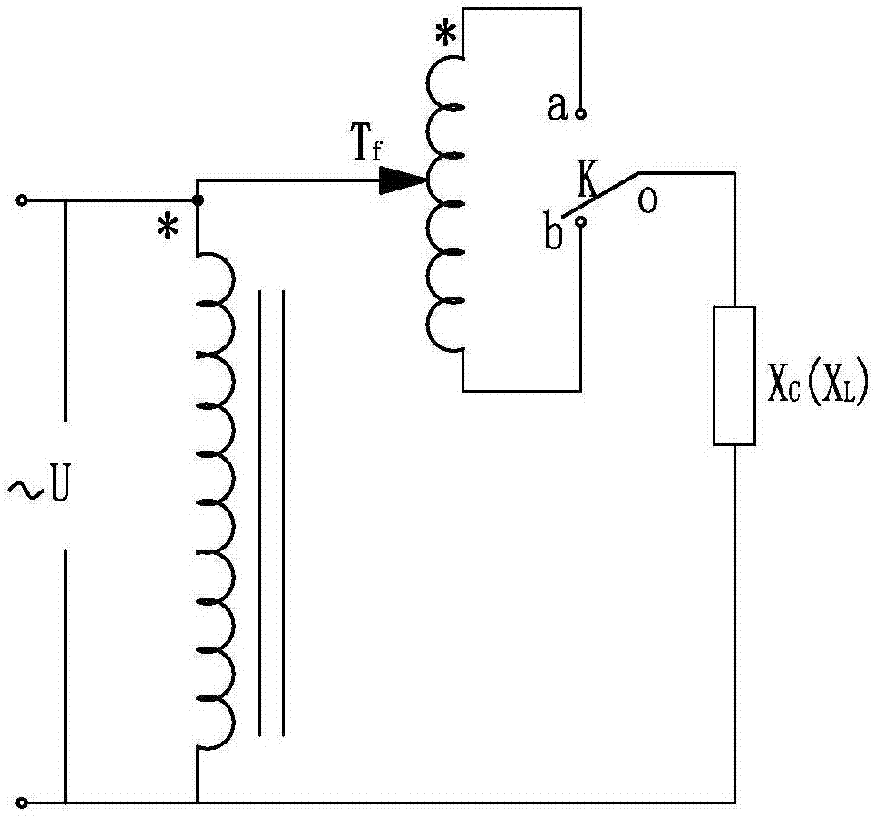
The invention relates to the reactive power compensation technology in a power grid and especially relates to a compensation device with the adjustment of a reactive power capacity by an autotransformer. The device comprises a switching selection switch K and an on-load tap-changer Tf. The autotransformer comprises a main winding and a voltage regulating winding. The voltage regulating winding whose number of turns is NT is independent of the nonadjustable main winding whose number of turns is NG. By using the mutual relation of the two windings, the same polarity direction access and reverse polarity direction access of the voltage regulating winding are realized through the switching selection switch K, thus the rated voltage UBe of the autotransformer can be matched with capacitor rated voltage UCe specified in national standards and industry standards, the ability of adjusting reactive power can reach required 6 to 7, at the same time even in a condition of same autotransformer capacity SBe and capacity adjustment ability M, the autotransformer electromagnetic capacity of the invention is only a half of that in a scheme in the prior art, the corresponding investment cost also can be reduced by nearly a half, thus the economic performance is closer to a fixed grouping method, the technical performance is better than that of fixed grouping method, the service life is longer, and the overall performance is greatly improved.

Description

technical field [0001] The invention relates to an on-site reactive power compensation technology in a power grid, in particular to a compensation device for adjusting reactive capacity of an autotransformer. Background technique [0002] With the increase of grid capacity, the demand for reactive power compensation capacity of the grid is also increasing day by day. Reactive power supply, like active power supply, is an indispensable part to ensure power system power quality, voltage quality, reduce network loss and safe operation. In the power system, the reactive power must be kept in balance. When the capacitive reactive power is insufficient, the system voltage will drop, the power factor of the network will decrease, and the electrical equipment will not be fully utilized, resulting in a decrease in network transmission capacity and increased loss. In severe cases, it will cause equipment damage and the system will be disconnected. Solving the problem of capacitive r...

Claims


Application Information

Patent Timeline
IPC IPC(8): H02J3/18
CPCH02J3/1878Y02E40/30
Inventor 罗明览林崇王劲军王致珍林红陈松华罗湘梅
Owner POWERCHINA FUJIAN ELECTRIC POWER SURVEY & DESIGN INST CO LTD
Why Eureka
Try Eureka