Pressure reducing device with temperature recovery function

A technology of decompression device and recovery function, applied in the direction of fluid pressure converter, mechanical equipment, etc., can solve the problems of energy waste, inability to compensate for unstable speed, etc., and achieve the effect of wide decompression range

Inactive Publication Date: 2012-10-24
BEIJING UNIV OF TECH
View PDF4 Cites 5 Cited by
  • Summary
  • Abstract
  • Description
  • Claims
  • Application Information

AI Technical Summary

Problems solved by technology

In addition, the throttle valve mainly controls the fluid flow by changing the throttle cross-sectional area or throttle length to achieve the depressurization effect, and cannot compensate for the speed

Method used


Image

  • Pressure reducing device with temperature recovery function
  • Pressure reducing device with temperature recovery function
  • Pressure reducing device with temperature recovery function

Examples


Embodiment Construction

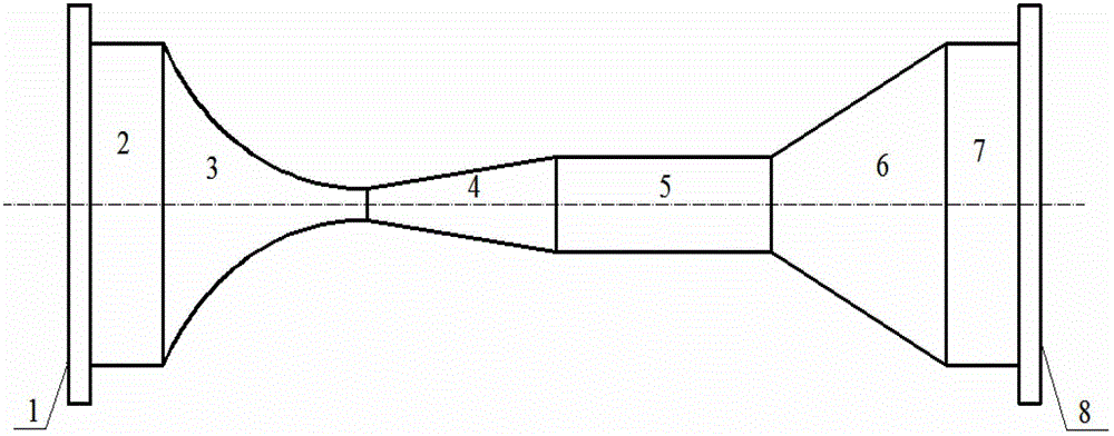
[0018] Below in conjunction with accompanying drawing the present invention is further described, and the present invention device comprises inlet flange 1, inlet straight pipe section 2, Rafael nozzle tapering section 3, Rafael nozzle expanding section 4, straight pipe section 5, diffuser section 6. Outlet straight pipe section 7. Outlet flange 8.

[0019] The device is connected to the main line of high-pressure fluid through the inlet flange 1 and outlet flange 8. At the same time, in order to prevent the fluid flowing into and out of the device from excessive turbulence, a certain length of smoothing is required at the inlet and outlet according to the flow rate. Straight section. The high-pressure compressible fluid first passes through the inlet straight pipe section and enters the tapering section 4. According to thermodynamic principles, at this stage, the fluid will accelerate, cool down, and depressurize, and reach a critical state at the throat. The fluid that has r...


PUM


Abstract

The invention relates to a pressure reducing device with a temperature recovery function. The pressure reducing device is applied to occasions where high-pressure compressible fluid needs to be converted into low-pressure fluid through throttling, and obvious temperature reduction is not allowed to occur, and belongs to the field of energy conservation and utilization. The pressure reducing device comprises an intake flange (1), an intake straight section (2), a laval nozzle taper section (3), a laval nozzle divergent section (4), a straight section (5), a diffusion section (6), a discharge straight section (7) and a discharge flange (8) which are connected continuously. The device has very broad pressure reduction range, has a compact structure and no moving parts, and is not easy to crack or leak.

Description

technical field [0001] The invention relates to a novel decompression device with temperature recovery function, constant flow rate and self-adaptive back pressure capability and a design method thereof. It is mainly used in occasions where high-pressure compressible fluid needs to be changed into low-pressure fluid through throttling and no obvious temperature drop is allowed, and belongs to the field of energy-saving utilization. Background technique [0002] In various production and processing processes such as petrochemical, power engineering, gas transportation and processing engineering, it is often necessary to convert high-pressure compressible fluids into low-pressure fluids to meet the requirements of downstream production processes. For example, the fluid produced from natural gas wells often has very high pressure and cannot directly enter the gathering and transportation system. It must be reduced to the allowable pressure of the gathering and transportation sy...

Claims


Application Information

Patent Timeline
IPC IPC(8): F15B3/00
Inventor 刘中良刘兴伟
Owner BEIJING UNIV OF TECH
Why Eureka
Try Eureka