Mould with diameter-variable rubber core and method for manufacturing diameter-variable rubber core by adopting mould
A mold and rubber core technology, which is applied in the mold field of variable diameter rubber cores, can solve the problems of stopping drilling, high labor intensity of well control personnel, and long delay time, so as to improve applicability, reduce labor intensity and improve work efficiency Effect
- Summary
- Abstract
- Description
- Claims
- Application Information
AI Technical Summary
Problems solved by technology
Method used
Image
Examples
Embodiment 1
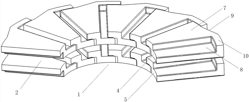
[0029] like Figure 1~6 The mold of a rubber variable-diameter rubber core is shown, and the mold includes an upper mold 11 and a lower mold 12 matched in size, an arc-shaped core mold (not shown) and an arc-shaped outer mold located on the core mold. The metal skeleton group 1 on the edge, the metal skeleton group 1 includes a plurality of metal skeleton units 2, each of the metal skeleton units 2 is provided with a fan-shaped connection part, and the adjacent metal skeleton units 2 pass through the fan-shaped connection part in turn The adjustable angle is connected to form a metal skeleton group 1 with a circular arc structure. The two ends of the metal skeleton group 1 are respectively provided with a block group 3, and the block group 3 connects the metal skeleton group 1 through a block pin 14. fixed, the core mold and the metal skeleton group 1 are located inside the lower mold 12, and the upper mold 11 is provided with a rubber injection tube 13, and the rubber injecti...
Embodiment 2
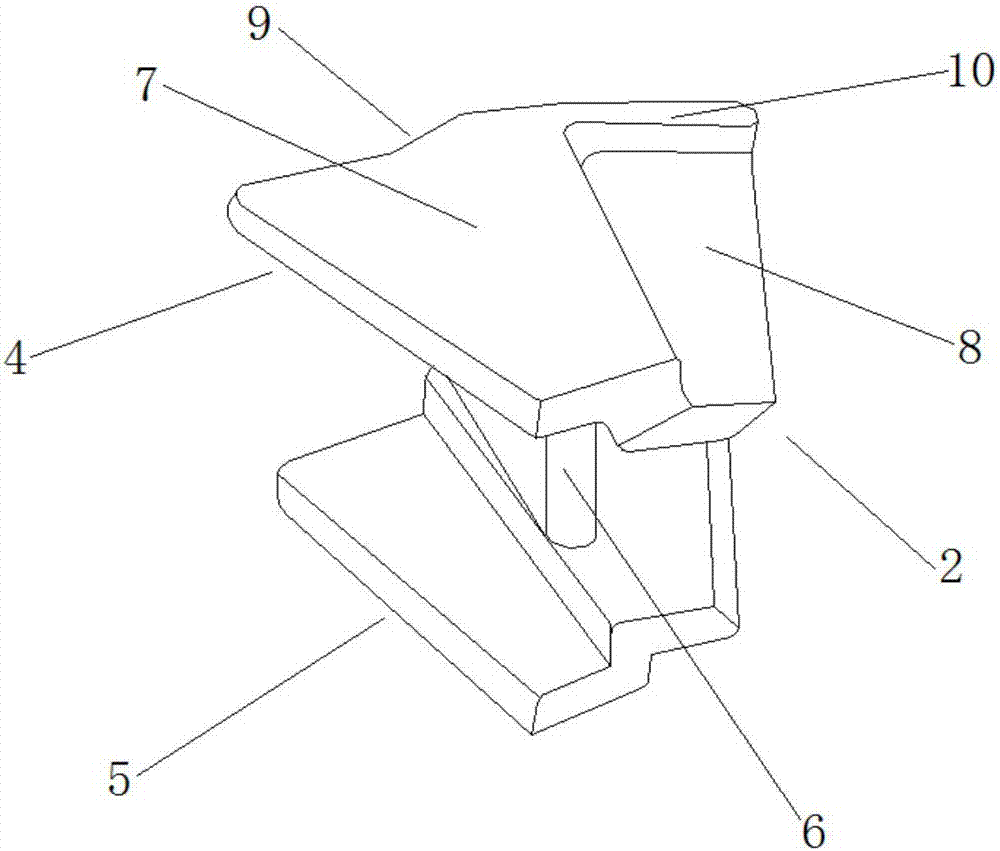
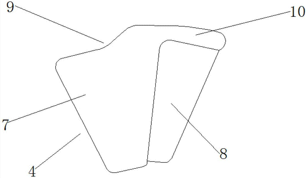
[0036]Based on Example 1, such as Figure 1~3 As shown, the fan-shaped connecting portion includes a symmetrically arranged upper fan-shaped connecting portion 4 and a lower fan-shaped connecting portion 5, the upper fan-shaped connecting portion 4 and the lower fan-shaped connecting portion 5 are connected by a metal connecting plate 6, and the upper fan-shaped connecting portion The connecting portion 4 and the lower fan-shaped connecting portion 5 all include a fan-shaped pressing block 7 and a fan-shaped step 8 arranged side by side, the fan-shaped pressing block 7 is higher than the fan-shaped step 8, and the outer edge of the fan-shaped pressing block 7 is provided with Groove 9, the edge of the fan-shaped step 8 is provided with a hook body 10 higher than the edge of the fan-shaped step 8, and the outer edge of the groove 9 matches the inner edge of the hook body 10 in size.
[0037] When the metal skeleton units 2 are arranged and connected in sequence, the fan-shaped ...
Embodiment 3
[0039] Based on Example 2, such as Figure 1~3 As shown, the central angle of the fan-shaped pressing block 7 is 20-40°, and the central angle of the fan-shaped step 8 is 20-40°, wherein it is more preferable that the central angle of the fan-shaped pressing block 7 is 30°, and the fan-shaped step 8 The central angle of 8 is 30°. It can ensure the angle-adjustable rotation connection when the fan-shaped pressing block 7 and the fan-shaped step 8 are connected, and then the radius of the metal skeleton group can be adjusted within a certain range.
PUM
| Property | Measurement | Unit |
|---|---|---|
| angle | aaaaa | aaaaa |
Abstract
Description
Claims
Application Information
 - R&D
- Intellectual Property
- Life Sciences
- Materials
- Tech Scout
- Unparalleled Data Quality
- Higher Quality Content
- 60% Fewer Hallucinations
Browse by: Latest US Patents, China's latest patents, Technical Efficacy Thesaurus, Application Domain, Technology Topic, Popular Technical Reports.
© 2025 PatSnap. All rights reserved.Legal|Privacy policy|Modern Slavery Act Transparency Statement|Sitemap|About US| Contact US: help@patsnap.com


