
Ultrahigh light supporting and retaining structure and method for treating high fill and high side slope engineering

A support structure, light technology, applied in infrastructure engineering, water conservancy engineering, underwater structures, etc., can solve the problems of no load-bearing and anti-slip, limited height of support and fill, and inappropriate use of anti-slip sections, etc. The construction is fast and simple, the overall coordination ability is good, and the maneuverability is flexible.

Pending Publication Date: 2017-08-29
HUNAN UNIV OF TECH
View PDF4 Cites 12 Cited by
  • Summary
  • Abstract
  • Description
  • Claims
  • Application Information

AI Technical Summary

Problems solved by technology

The disadvantages of the above retaining structure types are: on the one hand, the height of the retaining filling is limited; on the other hand, it only has the function of retaining soil, without load-bearing and anti-slip functions, and is not suitable for landslides, collapses, and soft soil foundations.
High and light anchor slab retaining wall is suitable for embankment retaining with filling height of 12.0m-16.0m, but it is not suitable for use in anti-slip sections

Method used


Image

  • Ultrahigh light supporting and retaining structure and method for treating high fill and high side slope engineering
  • Ultrahigh light supporting and retaining structure and method for treating high fill and high side slope engineering
  • Ultrahigh light supporting and retaining structure and method for treating high fill and high side slope engineering

Examples


Embodiment Construction

[0037] The following will clearly and completely describe the technical solutions in the embodiments of the present invention with reference to the accompanying drawings in the embodiments of the present invention. Obviously, the described embodiments are only some, not all, embodiments of the present invention. Based on the embodiments of the present invention, all other embodiments obtained by persons of ordinary skill in the art without making creative efforts belong to the protection scope of the present invention.

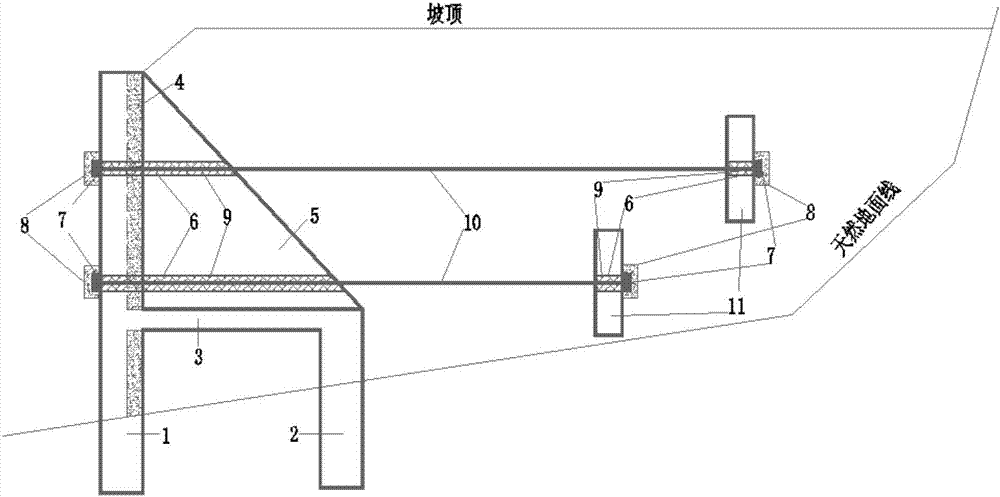
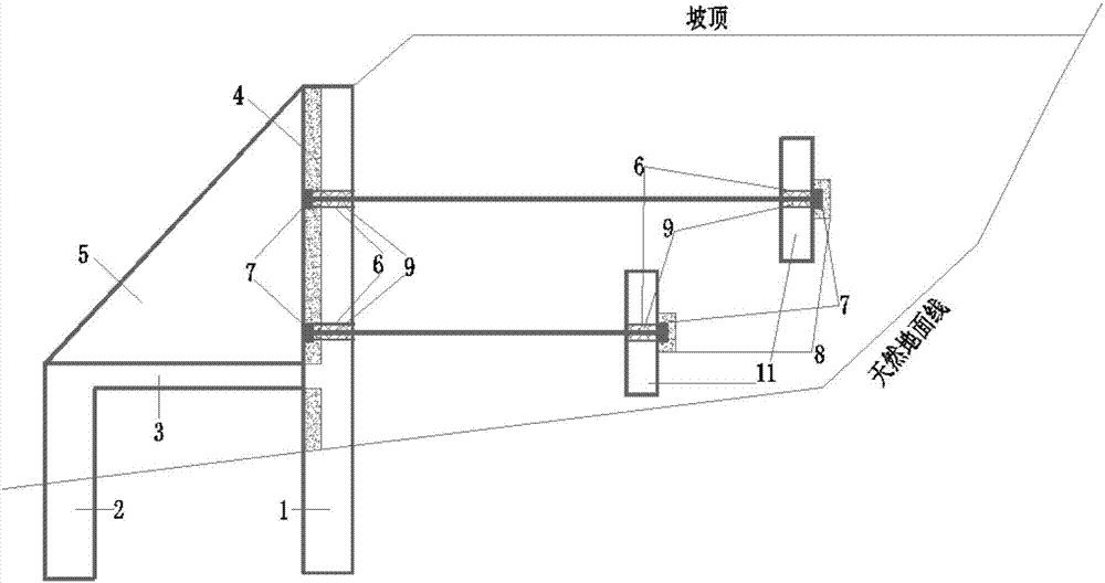
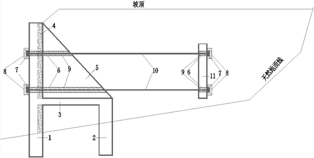
[0038] Ultra-high light retaining structure, the structure is as follows Figure 1-4 As shown in any form, including the vertical setting of the main pile 1 and the auxiliary pile 2 made of reinforced concrete, a cap 3 is arranged above the auxiliary pile 2 and between the main pile 1 and the auxiliary pile 2, and on the main pile 1 A retaining plate 4 made of reinforced concrete is provided; a support arm 5 is provided on the upper part of the main pile 1 and...


PUM

PropertyMeasurementUnit
Pile diameteraaaaaaaaaa
Thicknessaaaaaaaaaa
Thicknessaaaaaaaaaa

Abstract

The invention discloses an ultrahigh light supporting and retaining structure and a method for treating high fill and high side slope engineering. A main pile and an auxiliary pile are vertically arranged; then a part, below a bearing platform, of a soil retaining plate is constructed; filling soil between the piles and behind the piles is subjected to layered filling and compacted; the bearing platform is constructed; a support arm and the soil retaining plate above the bearing platform are constructed, steel pipes are pre-embedded; an anchor wall is constructed; the position behind the part, above the bearing platform, of the soil retaining plate is filled with soil; and pulling rods are positioned, mounted, tensioned and locked, anchor seal concrete is constructed, and cement slurry is poured into holes. The ultrahigh light supporting and retaining structure can be suitable for various site conditions; when the fill height is within 12.0-24.0 m and the total height of a side slope is within 16.0-30.0 m, the ultrahigh light supporting and retaining structure is comparable with a common soil retaining wall; when the fill height is within 24.0-30.0 m and the total height of the side slope is within 28.0-34.0 m, the ultrahigh light supporting and retaining structure is comparable with a bridge; and meanwhile, the ultrahigh light supporting and retaining structure has three functions of bearing, slipping resistance and soil retaining.

Description

technical field [0001] The invention belongs to the technical field of civil engineering, and relates to an ultra-high light retaining structure and a method for controlling high fill and high slope engineering. Background technique [0002] According to my country's "Code for Design of Highway Subgrade" (JTGD30-2004), the types and applicable conditions of retaining structures that can be used for filling slopes are as follows: 1) Gravity retaining walls (including counterweight retaining walls) are suitable for general areas Supporting works such as road shoulders, embankments and road cuttings in flooded areas and earthquake areas. The wall height is not more than 12.0m. 2) The semi-gravity retaining wall is suitable for the foundation with high groundwater level or weak ground where the gravity retaining wall is not suitable, and the wall height should not be greater than 12.0m. 3) The cantilever retaining wall should be used in the filling section with low foundation b...

Claims


Application Information

Patent Timeline
IPC IPC(8): E02D17/20E02D29/02
CPCE02D17/207E02D29/02E02D29/0233
Inventor 刘杰唐西娅杨庆光
Owner HUNAN UNIV OF TECH
Learn More