
Reciprocating friction-wear test apparatus and method

A friction and wear test, reciprocating technology, applied in the direction of testing wear resistance, etc., can solve the problems of poor reciprocating motion stability, multi-stage coupling piston, tripping, etc., to ensure the accuracy of stroke control and meet the quantitative evaluation requirements , to ensure the effect of stability

Pending Publication Date: 2017-08-29
CHINA PETROLEUM & CHEM CORP +1
View PDF9 Cites 6 Cited by
  • Summary
  • Abstract
  • Description
  • Claims
  • Application Information

AI Technical Summary

Problems solved by technology

However, due to the structural characteristics of the ordinary steel rod itself, especially the tripping, fracture and multi-stage coupling piston effect caused by the eccentric wear of the sucker rod coupling, the steel rod has some insurmountable weaknesses.
[0003] For this reason, the research direction at home and abroad has turned to continuous sucker rods, mainly steel continuous rods, flexible continuous rods and carbon fiber composite continuous rods, etc., but there are relatively few studies on the friction and wear properties of continuous rods.
Through the investigation of friction and wear testing machines at home and abroad, it is concluded that: although the current friction and wear testing devices have realized the experimental simulation of the eccentric wear of oil well rods and tubes under the condition of reciprocating motion, they mostly use eccentric wheel-tie rod, hydraulic pressure-reciprocating pump and other working forms. The stability of reciprocating motion is poor, and the accuracy of motion stroke control is low
In addition, none of the existing friction and wear test devices can simulate the working environment of rods and tubes, and the accuracy of the test results is not high

Method used


Image

  • Reciprocating friction-wear test apparatus and method
  • Reciprocating friction-wear test apparatus and method

Examples


Embodiment Construction

[0019] The detailed description and technical content of the present invention are described below with the accompanying drawings, but the accompanying drawings are only provided for reference and description, and are not intended to limit the present invention.

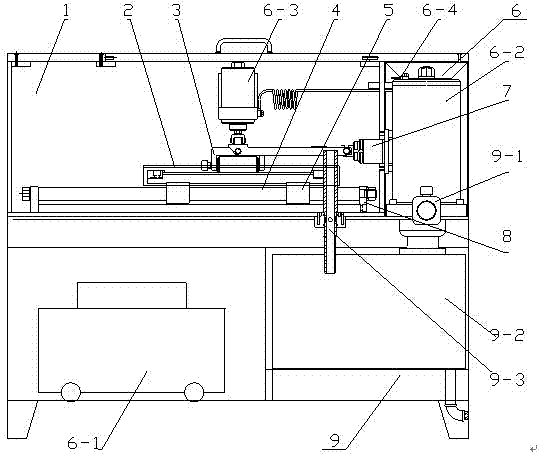
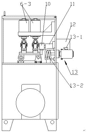
[0020] according to Figure 1-2 , a reciprocating friction and wear test device, including a test chamber 1, a tubing clamping part 2, a specimen clamping part 3, a tubing reciprocating sliding system, a loading system 6, a friction sensor 7, a medium circulation system 9, and a temperature control system 13. The oil pipe clamping part and the test piece clamping part are all arranged in the test chamber 1, and after the oil pipe clamping part and the test piece clamping part hold the oil pipe and the test piece respectively, press the test piece on the oil pipe The oil pipe clamping part and the oil pipe are connected together on the oil pipe reciprocating sliding system, a loading system 6 acts on the specimen clam...


PUM


Abstract

The invention discloses a reciprocating friction-wear test apparatus and method. The apparatus includes a test box, an oil pipe clamping part, a test piece clamping part, an oil pipe reciprocating slide system, a loading system, a frictional force transducer, a medium circulation system and a temperature control system. The oil pipe clamping part and the test piece clamping part are all arranged in the test box, and after the oil pipe clamping part clamps an oil pipe and the test piece clamping part clamps a test piece, the test piece presses the oil pipe. The oil pipe clamping part and the oil pipe are all connected to the oil pipe reciprocating slide system. The loading system is acted on the test piece clamping part, and the frictional force transducer is acted on the oil pipe clamping part. The medium circulation system communicates with the test box, and the temperature control system is installed on the test box for controlling the temperature of a test medium. The apparatus simulates the actual working condition of a sucker rod and oil pipe frictional pair in an oil well and can accurately evaluate the wear resistance of a pipe rod material, so that guide is provided for adopting specific anti-eccentric wear measures for anti-eccentric wells.

Description

technical field [0001] The invention relates to a friction and wear testing machine for oil fields, in particular to a reciprocating friction and wear testing device and method. Background technique [0002] With the development of the oil field, the working conditions of the sucker rod become very bad due to the influence of factors such as water content, temperature, well deviation, etc., and the resulting wear failure accident caused by eccentric wear between the sucker rod and the tubing also greatly increased. In order to meet the needs of oilfield production, each manufacturer started with materials, surface treatment and production technology, and proposed some measures to reduce the eccentric wear of rods and pipes to prolong the repair-free period of oil wells. However, due to the structural characteristics of the ordinary steel rod itself, especially the tripping, fracture and multi-stage coupling piston effect caused by the eccentric wear of the sucker rod coupli...

Claims


Application Information

Patent Timeline
IPC IPC(8): G01N3/56
CPCG01N3/56
Inventor 汪云家贾庆升张雷姜东张中慧刘晓玲杨斌郑强黄润晶于雪林王慧莉
Owner CHINA PETROLEUM & CHEM CORP
Learn More