Plain bearing and method for producing same

A technology of sliding bearings and shaft holes, which is applied in the field of sliding bearings and pumps, can solve the problems of increased impeller rotational torque, decrease and increase of pump capacity, and achieve the effect of suppressing the increase of impeller rotational torque and reducing sliding resistance

Active Publication Date: 2017-08-29
EAGLE INDS
View PDF12 Cites 9 Cited by
  • Summary
  • Abstract
  • Description
  • Claims
  • Application Information

AI Technical Summary

Problems solved by technology

At this time, since the sliding resistance of the sliding bearing against the restricting member (sliding resistance between the sliding bearing and the opposing surface of the restricting member) increases, the rotational torque of the impeller increases and the pump capacity decreases.

Method used


Image

  • Plain bearing and method for producing same
  • Plain bearing and method for producing same
  • Plain bearing and method for producing same

Examples


Embodiment 1

[0054] A sliding bearing and a pump according to Embodiment 1 of the present invention will be described with reference to the drawings. In addition, in this embodiment, an electric water pump used for pressure-feeding cooling water in a hybrid vehicle or the like will be described as an example. Therefore, in this embodiment, the fluid pumped is cooling water.

[0055]

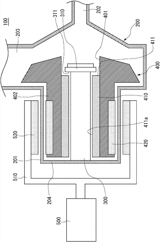
[0056] refer to figure 1 , illustrating the overall structure of the pump of the embodiment of the present invention. figure 1 It is a schematic sectional view of the pump 100 according to the embodiment of the present invention, and is a schematic sectional view cut along a plane including the central axis of the shaft 300 . In addition, for convenience of description, the internal structure is omitted, and basically only the end faces are shown.

[0057]The pump 100 includes a housing 200 , a shaft 300 provided in the housing 200 , and an impeller 400 that rotates with respect to the shaft 300 and pump...

Embodiment 2

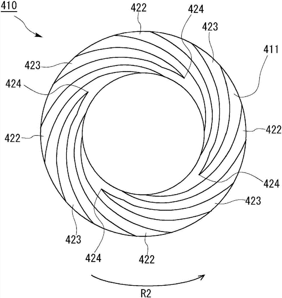
[0073] Then, refer to image 3 Example 2 of the present invention will be described. In this embodiment, only the shapes of the lubricating groove and the dynamic pressure generating groove provided on the end surface 411 of the sliding bearing 410 are different from the shape of the above-mentioned embodiment 1, and the other structures are the same. Therefore, differences will be described below, and descriptions of other structures and functions will be omitted. Also use the same symbol for the same structural part.

[0074] image 3 with the above figure 2 Similarly, it is a diagram when the sliding bearing 410 is viewed from the restricting member 310 side in the axial direction, and shows the structure of the end surface 411 . A lubricating groove 422 and a dynamic pressure generating groove 423 are formed on the end face 411. The lubricating groove 422 communicates with the inner and outer sides in the radial direction, and cooling water is supplied to the end face...

Embodiment 3

[0092] Next, refer to Figure 16 , to illustrate Embodiment 3 of the present invention. The present embodiment differs from the structure of the above-described first embodiment only in that restricting members serving as restricting portions for restricting the axial movement of the sliding bearing 410 are provided on both axial sides of the sliding bearing 410 , and the other structures are the same. Therefore, only the different points will be described below, and descriptions of other structures and functions will be omitted. In addition, the same symbol is used for the same structural part.

[0093] Figure 16 with the above figure 1 Similarly, it is a schematic cross-sectional view of the pump 110 of this embodiment. Pump 110 is equipped with figure 1 In addition to the configuration of the pump 100 shown, a restricting member 320 as a second annular restricting portion is further provided. The restricting portion 320 is fixed to the left side surface 204 in the dr...


PUM


Abstract

A bearing 10 comprises: a half bearing member having an inner peripheral surface against which slides a corresponding shaft, and a plurality of recesses provided to a first end surface in the axial direction of said opposing shaft; a first flange member having a plurality of protrusions provided at positions corresponding to the plurality of recesses provided to the first end surface; and a plurality of crimping marks respectively formed in the periphery of each recess when crimping the recess with the plurality of protrusions on the first end surface engaged with the plurality of recesses in order to fix the first flange member to the half bearing member. With regard to the crimping marks that are formed on both sides of at least one of the plurality of recesses, the volume of the deformed part of the crimping mark positioned to the outside in the circumferential direction when viewed from the radial direction of the opposing shaft, is smaller than the volume of the deformed part of the crimping mark positioned to the inside.

Description

technical field [0001] The invention relates to a sliding bearing and a pump. Background technique [0002] The invention relates to a sliding bearing and a pump. [0003] Conventionally, there are known pumps in which a fluid is pressure-fed by an impeller rotating with respect to a shaft provided in a housing (refer to Patent Documents 1 and 2). In a pump having such a structure, an annular sliding bearing is used to support the impeller rotatably relative to the shaft. Here, when the sliding bearing is fixed to the impeller, the sliding bearing moves in the axial direction (axial direction) relative to the shaft. Therefore, in order to restrict the axial movement of the sliding bearing, an annular restricting member (washer, etc.) fixed to the shaft is used. [0004] However, when the rotation speed of the impeller is high, the impeller moves toward the restricting member. At this time, since the sliding resistance of the sliding bearing against the restricting member...

Claims


Application Information

Patent Timeline
Patent Type & Authority Applications(China)
IPC IPC(8): F16C17/10F04B53/00F04D13/02F04D29/046F16C33/10
CPCF04B53/00F16C17/10F16C17/045F16C17/107F04D13/0633F04D29/0473F05D2240/53F04D29/061F16C33/107F16C2360/44F16J15/3412F04D29/0413F16C33/1045F04D29/047F16C32/06F04D13/02F04D29/046F04D1/00F04D29/22F04D29/426
Inventor 山本真也安悟史细江猛德永雄一郎千叶启一
Owner EAGLE INDS
Why Eureka
Try Eureka