Heat storage container and heat storage device including heat storage container

A heat storage device and container technology, applied in heat storage equipment, indirect heat exchangers, heat exchanger types, etc., can solve problems such as complex piping structure, reduced heat utilization, and inability to increase heat

Active Publication Date: 2019-08-13
FURUKAWA ELECTRIC CO LTD
View PDF8 Cites 0 Cited by
  • Summary
  • Abstract
  • Description
  • Claims
  • Application Information

AI Technical Summary

Problems solved by technology

However, in the heat storage container 6 of Patent Document 1, since it is necessary to separately provide the reaction channel 64 for supplying water vapor and the heat exchange channel 66 for supplying the heat exchange medium, there is a problem that the piping structure becomes complicated.
In addition, since the amount of the chemical heat storage material 62 that can be mounted on the heat storage container 6 decreases due to the complexity of the piping structure, there is a problem that the heat utilization per unit volume of the heat storage container 6 (heat storage density) decreases.
[0004] In addition, in the heat storage container 6 of Patent Document 1, if a gaseous fluid is used as the heat exchange medium, only sensible heat can be supplied to the gaseous fluid, so the heat transfer amount of the heat exchange medium is limited. In addition, there is also the following problem: In order to supply the gaseous heat exchange medium to the heat storage container 6 and to prevent the temperature drop of the heat exchange medium storage container due to the heat of vaporization, it is necessary to inject energy, in addition, there is also the following problem: if gas such as water vapor is used as the reaction fluid, the heat released from the chemical heat storage material 62 cannot be improved.
However, if a liquid such as water is used as a reactive fluid, there is a problem that even if a powdery chemical heat storage material is compression-molded, the shape of the chemical heat storage material will be destroyed due to repeated heat release and heat storage. This will cause the chemical heat storage material to flow out of the heat storage container
[0006] It should be noted that there is a problem that when a heat storage device is provided with a heat storage container using a liquid such as water as a reaction fluid in a circulation system of an airtight and degassed reaction fluid, sometimes The reaction fluid vaporized in the heat storage container will flow back to the side of the reaction fluid storage tank provided in the heat storage device and used to supply the reaction fluid to the heat storage container, making it difficult for the reaction fluid to transfer heat to the heat utilization target. Condenser side flow of connected heat storage unit

Method used


Image

  • Heat storage container and heat storage device including heat storage container
  • Heat storage container and heat storage device including heat storage container
  • Heat storage container and heat storage device including heat storage container

Examples


Embodiment Construction

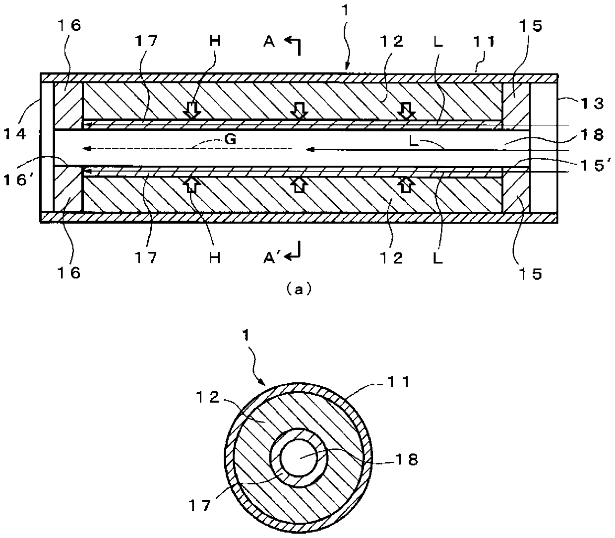
[0069] Next, the thermal storage container according to the first embodiment of the present invention will be described with reference to the drawings. Such as figure 1 As shown in (a), the heat storage container 1 according to the first embodiment includes: a cylindrical body 11 which is a tubular body with openings at both ends; internal. In addition, the heat storage container 1 includes: a first cover 15, which is arranged adjacent to the one end 13 side of the cylindrical body 11 of the chemical heat storage material 12, and is made of a porous body; a second cover 16, which The other end portion 14 of the cylindrical body 11 of the chemical heat storage material 12 is disposed adjacent to and made of a porous body; The diffusion layer for transporting the liquid disposed adjacent to the inner side surface of the chemical heat storage material 12 between the second covers 16 has a capillary structure.

[0070] Such as figure 1 As shown in (b), the radial cross secti...


PUM


Abstract

There is provided a heat storage system and a heat storage container each capable of improving a heat generation amount and a heat transport amount with a simple configuration, and a heat storage device using the above heat storage container. A heat storage system using a heat storage container having a tubular body, a chemical heat storage material accommodated in the tubular body, and a flow channel that penetrates the tubular body in a longitudinal direction, the heat storage system having a diffusion layer for transporting liquid from the flow channel to the chemical heat storage material, the liquid functioning as a reaction medium of the chemical heat storage material, wherein the liquid is transported to the flow channel, the liquid is transported to the diffusion layer, the liquid transported to the diffusion layer reacts with the chemical heat storage material, the chemical heat storage material generates heat, and the liquid is vaporized by the heat to become heat transport fluid.

Description

technical field [0001] The present invention relates to a heat accumulator using a chemical heat storage material and a heat storage device including the heat accumulator. The reverse reaction of endothermic reversible reaction, heat release and heat storage are repeated. Background technique [0002] The heat storage amount per unit volume of the chemical heat storage material is large, and even if the chemical heat storage material after heat storage is stored for a long time, the heat loss is extremely small. Storage and utilization of heat discharged from industrial plants (plants). [0003] Therefore, if Figure 8 As shown, a heat storage container 6 is proposed in which a chemical heat storage material complex including a powdery chemical heat storage material 62 and a foaming expansion material 63 arranged adjacent to the chemical heat storage material 62 is housed in an inner tube 61 Between the outer tube 67 and the chemical heat storage material 62, the reaction ...

Claims


Application Information

Patent Timeline
Patent Type & Authority Patents(China)
IPC IPC(8): F28D20/00C09K5/16F28D15/02F28D15/04F28D15/06
CPCC09K5/16F28D15/02F28D20/003F28D2020/0013Y02E60/14F28D15/04F28D15/046F28D15/06F28D2020/0069
Inventor 岛田守鲇泽恒志中村敏明池田匡视立石徹
Owner FURUKAWA ELECTRIC CO LTD
Why Eureka
Try Eureka