Power generation device
A technology of a power generation device and a Stirling engine, which is applied to machines/engines, mechanical equipment, and mechanisms that generate mechanical power, etc., can solve the problems of difficult processing technology, poor economy, and inconvenient production, and achieve high power scalability. and economical effects
- Summary
- Abstract
- Description
- Claims
- Application Information
AI Technical Summary
Problems solved by technology
Method used
Image
Examples
specific Embodiment 1
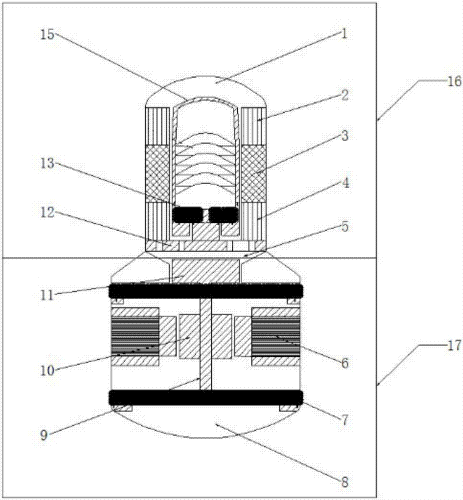
[0056] The phase adjustment mechanism 300 of the present invention is an acoustic resonance tube. One end of the acoustic resonance tube is closed, and the other end is open. The output end of the Stirling engine 100 is connected to the open end of the acoustic resonance tube in a closed manner. The two-way turbine generator 200 is installed in the acoustic resonance tube, such as Picture 9 As shown, the two-way turbine power generation device 200 can be installed at any position between the maximum point of the volume flow rate in the acoustic resonance tube.
[0057] That is, during the working process, the Stirling engine 100 converts heat energy into sound energy, and by realizing the acoustic impedance matching of the two-way turbine generator with significant acoustic resistance characteristics and the Stirling engine whose outlet requires acoustic resistance plus acoustic characteristics, After passing through the two-way turbine power generation device 200, it is conver...
specific Embodiment 2
[0060] The phase adjustment mechanism 300 of the present invention is an acoustic resonance tube. Both ends of the acoustic resonance tube are open. The output end of the Stirling engine 100 is connected to the open end of the acoustic resonance tube in a closed manner, and an air reservoir 400 is installed to the other open end of the acoustic resonance tube. The two-way turbine power generation device 200 is installed at the entrance of the gas store 400, such as Picture 10 Shown.
[0061] That is, during the working process, the Stirling engine 100 converts thermal energy into sound energy, and realizes the two-way turbine generator 200 with significant acoustic resistance characteristics through the acoustic resonance tube and the Stirling engine whose outlet requires acoustic resistance plus acoustic characteristics. Acoustic impedance is matched, and it is converted into electrical energy output through the two-way turbine generator 200.
[0062] In this embodiment, the ai...
specific Embodiment 3
[0067] As another specific embodiment of the present invention, a power generation device of the present invention includes a Stirling engine 100, a phase modulation mechanism 300 and a two-way turbine power generation device 200, wherein the phase modulation mechanism 300 in this embodiment is a resonator . The output end of the Stirling engine 100 is connected in a closed manner with a connecting pipe 500. The end of the connecting pipe 500 is connected with an air reservoir 400. The resonator and the two-way turbine generator 200 are respectively installed in the connecting pipe 500, and the Stirling The engine 100 is connected to the two-way turbine generator 200 through a resonator. In order to further improve its efficiency, the two-way turbine power generation device 200 of the present invention is preferably installed at the entrance of the gas storage.
[0068] The present invention utilizes the Stirling engine 100 to convert heat energy into sound energy, and realizes ...
PUM
 Abstract
Description
Claims
Application Information
 - R&D
- Intellectual Property
- Life Sciences
- Materials
- Tech Scout
- Unparalleled Data Quality
- Higher Quality Content
- 60% Fewer Hallucinations
Browse by: Latest US Patents, China's latest patents, Technical Efficacy Thesaurus, Application Domain, Technology Topic, Popular Technical Reports.
© 2025 PatSnap. All rights reserved.Legal|Privacy policy|Modern Slavery Act Transparency Statement|Sitemap|About US| Contact US: help@patsnap.com


