Pure water hydraulic drive system of lifting platform

A driving system and lifting platform technology, applied in the direction of fluid pressure actuators, accumulator devices, servo motors, etc., can solve pollution, flammability and other problems, to improve safety, reduce installed power, and high reliability Effect

Active Publication Date: 2017-09-01
ZHEJIANG UNIV
9 Cites 3 Cited by

AI-Extracted Technical Summary

Problems solved by technology

[0005] The purpose of the present invention is to provide a pure water hydraulic drive system for a lifting platform, which solves the two major problems of pollution and flammability in the traditional h...

Abstract

The invention discloses a pure water hydraulic drive system of a lifting platform. Deionized water is used as a hydraulic transmission medium. The pure water hydraulic drive system comprises a water pressure piston cylinder, a three-position four-way electromagnetic reversing valve, a proportional valve, an energy accumulator, a check valve, a hydraulic control check valve, a plunger water pump, a variable frequency motor, an overflow valve, a filter and a water tank. The movement state of the hydraulic cylinder is regulated in real time through the three-position four-way electromagnetic reversing valve and the proportional valve, and the movement speed of the lifting platform is precisely controlled. For the heavy load requirement of the lifting platform, the energy accumulator is used as an auxiliary power source, an energy accumulator unloading loop is designed, and the service life of the energy accumulator is prolonged while the installed power of the system is lowered. By means of the pure water hydraulic drive system, the pure water hydraulic technology is applied in the lifting platform, the special loop is designed for the specificity of water pressure components, and the pure water hydraulic drive system can be widely applied to high-temperature open fire radiation places and various lifting platforms under the flammable and combustible pollution-free environments and other environments.

Application Domain

Accumulator installationsServomotors +1

Technology Topic

Piston cylinderOpen fire +14

Image

  • Pure water hydraulic drive system of lifting platform

Examples

  • Experimental program(1)

Example Embodiment

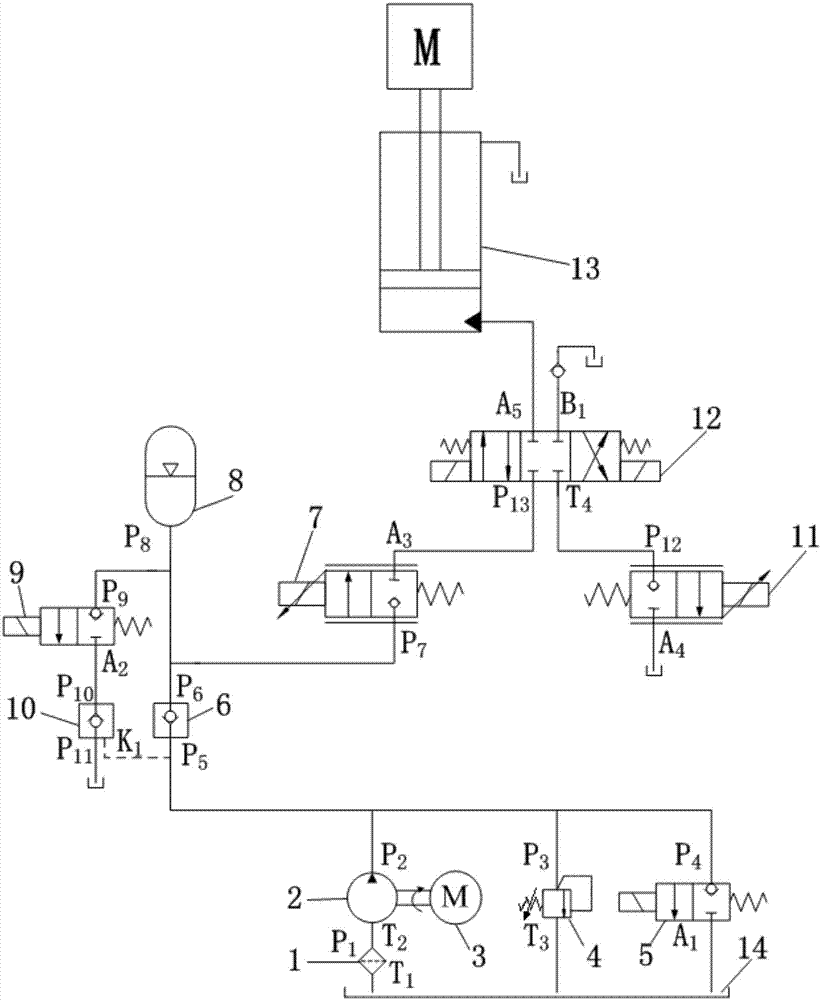
[0012] as attached figure 1 As shown, the pure water hydraulic drive system of the lifting platform of the present invention includes: filter 1, plunger pump 2, frequency conversion motor 3, overflow valve 4, first two-position two-way reversing valve 5, one-way valve 6, first Proportional valve 7, accumulator 8, second two-position two-way reversing valve 9, hydraulic control check valve 10, second proportional valve 11, three-position four-way reversing valve 12, hydraulic cylinder 13, water tank 14.
[0013] Among them, the variable frequency motor 3 is connected with the plunger pump 2 to drive the plunger pump 2 to work, and the water inlet T of the filter 1 1 Connected with the water tank 14, the water outlet P of the filter 1 1 With the suction port T of the plunger pump 2 2 Connected, outlet P of plunger pump 2 2 Inlet P with overflow valve 4 3 , the water inlet P of the first two-position two-way reversing valve 5 4 , Water inlet P of check valve 6 5 , the control water port K of the hydraulic control check valve 10 1 Connected, outlet T of overflow valve 4 3 , Outlet A of the first two-position two-way reversing valve 5 1 Connected with the water tank 14, the water outlet P of the one-way valve 6 3 With the water inlet P of the first proportional valve 7 7 , water port P of accumulator 8 8 , the water inlet P of the second two-position two-way reversing valve 9 9 Connected, outlet A of the second two-position two-way reversing valve 9 2 With the water inlet P of the hydraulic control check valve 10 10 Connected, the water outlet P of the hydraulic control check valve 10 11 Connected with the water tank 14, the water outlet A of the first proportional valve 7 3 With the water inlet P of the three-position four-way reversing valve 12 13 Connected, the first working water port A of the three-position four-way reversing valve 12 5 It communicates with the rodless cavity of the hydraulic cylinder 13, and the second working water port B of the three-position four-way reversing valve 12 1 In a blocked state, the water return port T of the three-position four-way reversing valve 12 4 With the water inlet P of the second proportional valve 11 12 connected, the water outlet A of the second proportional valve 11 4 It communicates with the water tank 14, and the hydraulic cylinder has a rod cavity that directly communicates with the water tank 14. .
[0014] Working process of the present invention is as follows:
[0015] In the initial state, the first two-position two-way reversing valve 5, the first proportional valve 7, the second two-position two-way reversing valve 9, the second proportional valve 11, and the three-position four-way reversing valve 12 are all powered off state, the hydraulic cylinder 13 is in a locked state, and the lifting platform is still at this moment. The pumping station system is powered on and starts to work. The pumping station system adopts the power source mode of single pump + frequency conversion speed regulation + overflow valve for water supply. At the same time, in order to improve the filtration accuracy and reduce system failures, filter is added at the pump suction port. First, the frequency conversion motor 3 starts to drive the plunger pump 2 to work, and the high-pressure water output by the plunger pump enters the interior of the accumulator through the one-way valve 6 to complete the flushing process of the accumulator. When the accumulator needs to be unloaded, the motor pump stops working, and the first two-position two-way reversing valve 5 is energized to complete the control of the water port K by the hydraulic control check valve 10 1 Here, the second two-position two-way reversing valve 9 is energized to work, and the high-pressure water in the accumulator flows back to the water tank through the second two-position two-way reversing valve 9 and the hydraulic control check valve 10 in turn. , to complete the unloading work of the accumulator.
[0016] Platform rising process: The pure water hydraulic drive system starts to work. The system uses a three-position four-way reversing valve and a normally closed proportional valve in the pure water hydraulic pressure to accurately control the movement speed of the piston rod of the hydraulic cylinder. The first proportional valve 7 and the left electromagnet of the three-position four-way reversing valve 12 are energized, and the high-pressure water output by the plunger pump passes through the one-way valve 6, the first proportional valve 7, and the three-position four-way reversing valve 12 to enter the hydraulic pressure. The rodless chamber of the hydraulic cylinder pushes the piston to move upward, and the water in the rod chamber of the hydraulic cylinder directly flows back to the water tank. The upward speed of the platform is adjusted through the first proportional valve 7 to meet the system design requirements.
[0017] The platform descending process: the platform descends by its own weight, the second proportional valve 11 and the right solenoid of the three-position four-way reversing valve 12 are energized, and the high-pressure water in the rodless chamber of the hydraulic cylinder begins to unload, and the three-position four-way reversing Valve 12, two second proportional valves 11 flow back to the water tank, and the piston descends under the action of gravity. The variation law and final speed of the descending speed of the piston are adjusted by the second proportional valve 11, which can ensure that the platform moves smoothly in the process of descending.

PUM

no PUM

Description & Claims & Application Information

We can also present the details of the Description, Claims and Application information to help users get a comprehensive understanding of the technical details of the patent, such as background art, summary of invention, brief description of drawings, description of embodiments, and other original content. On the other hand, users can also determine the specific scope of protection of the technology through the list of claims; as well as understand the changes in the life cycle of the technology with the presentation of the patent timeline. Login to view more.

Similar technology patents

Control system and method for motor vehicles

InactiveUS20040084002A1improve reliabilityspeed and stability
Owner:TOYOTA JIDOSHA KK

Installation management method, server and terminal for application program

InactiveCN102446106Aprevent crackingImprove reliability
Owner:LENOVO (BEIJING) CO LTD

Forest fireproof monitoring and patrolling system

Owner:内蒙古亨利新技术工程股份有限公司

Unmanned aerial vehicle flight control system having multisensor redundant backup

ActiveCN105867414AIncrease flight control weight and costImprove reliability
Owner:ZHEJIANG UNIV

Classification and recommendation of technical efficacy words

  • Improve reliability
  • Reduce installed power

Multiple branch predictions

ActiveUS20050268075A1improve reliabilityfacilitate availability
Owner:ORACLE INT CORP

Implantable lead

ActiveUS20100137928A1good flexibility , fatigue resistance and flex lifeimprove reliability
Owner:WL GORE & ASSOC INC

Rapid hydraulic press system used for hot-stamping forming of high-strength steel plate

InactiveCN102641935Awork fasterReduce installed power
Owner:山东大王金泰集团有限公司
Why Eureka
Try Eureka