
Low-cost electromagnetic heating heat supply device

A heating device and low-cost technology, applied in the field of low-cost electromagnetic heating heating devices, can solve the problems of low thermal efficiency, pollute the environment, insufficient pressure bearing capacity, etc., and achieve the effect of reducing costs

Pending Publication Date: 2017-09-01
天津市坤宇清源科技有限公司
View PDF5 Cites 1 Cited by
  • Summary
  • Abstract
  • Description
  • Claims
  • Application Information

AI Technical Summary

Problems solved by technology

[0002] Common boilers in existing heating systems usually use coal, fuel oil, gas and electric energy as energy sources for heating. Coal, fuel oil and gas are non-renewable resources, and the heating efficiency is low, and a large amount of pollution is generated during the combustion process. Moreover, the thermal efficiency is low, the energy consumption is high, and the boiler water tank, cold wall pipe, flue gas pipe and other places are prone to fouling, and the boiler needs to be shut down frequently for cleaning; the boiler is installed at the outlet of the circulating pump, so that the boiler has been working under high pressure Due to the corrosion of the boiler by the impurities in the water in the process of use, the pressure bearing strength of the boiler gradually decreases, and there is a safety hazard of insufficient pressure bearing capacity; once a power failure occurs, the water in the boiler will stop circulating immediately, and the waste heat in the boiler will be Continue to heat the hot water, so that the hot water that has stopped circulating in the boiler heats up rapidly, and when it reaches a certain temperature, it starts to vaporize, and even safety accidents such as boiler explosions occur

Method used


Image

  • Low-cost electromagnetic heating heat supply device

Examples


Embodiment Construction

[0026] The present invention will be further described in detail below in conjunction with the accompanying drawings and specific embodiments. It should be noted that: the following examples are illustrative, not limiting, and the protection scope of the present invention cannot be limited by the following examples.

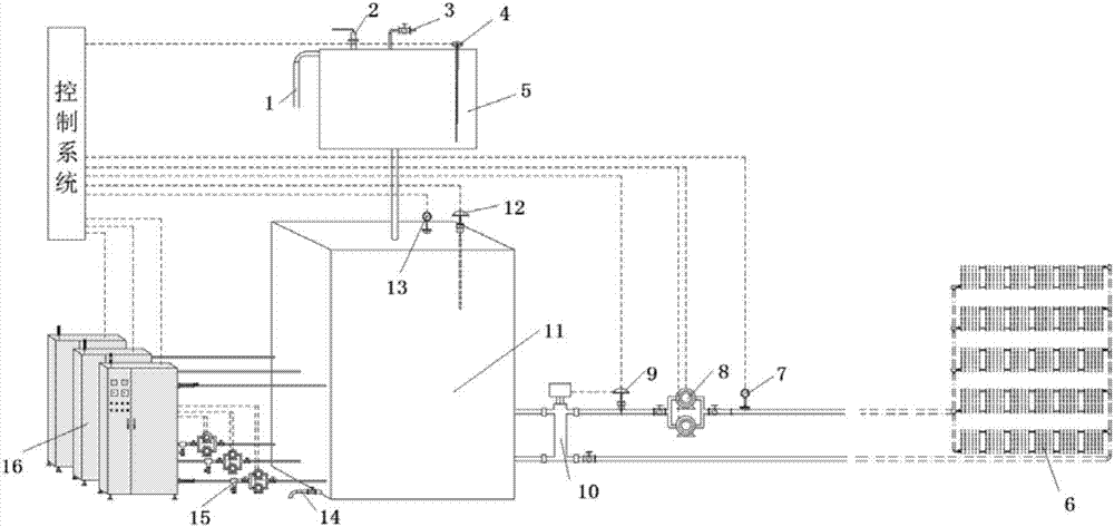
[0027] see figure 1 Shown is a specific embodiment of a low-cost electromagnetic heating heating device of the present invention. It can be seen that the present invention includes an electromagnetic heating boiler group 16, a heat storage tank 11 and an overflow tank 5; The heating pipeline is connected with the electromagnetic heating boiler group 16, and the hot water storage tank 11 is connected with the overflow tank 5 through the overflow pipeline. The electromagnetic heating boiler group 16 includes three electromagnetic heating boilers, and each electromagnetic heating boiler separately controllable.

[0028] The electromagnetic heating boiler group 16 i...


PUM


Abstract

The invention discloses a low-cost electromagnetic heating heat supply device which comprises an electromagnetic heating boiler group, a heat storage water tank and an overflow tank. The heat storage water tank is connected with the electromagnetic heating boiler group through a heating cycle water pump set and connected with the overflow tank through a pipeline. According to the low-cost electromagnetic heating heat supply device, microcrystal surfaces arranged on the inner walls of steam generators of electromagnetic heating boilers are not prone to scaling, and the electromagnetic heating boilers are free of combustion high temperature flame through electromagnetic heating, free of burst hidden danger through liquid-electricity separation and environmentally friendly; the heat storage water tank is connected with the overflow tank which stores water overflowing out of the heat storage water tank due to heating expansion, and burst due to excess pressure is avoided; one end of a water inlet pipe is provided with an arc bend which applies stirring force on the water in the heat storage water tank, and mixing of the high temperature water and the low temperature water in the heat storage water tank is achieved; and the electromagnetic heating boilers can be selectively turned on, the service lives are prolonged, and cost is reduced.

Description

technical field [0001] The invention relates to a heating system, in particular to a low-cost electromagnetic heating heating device. Background technique [0002] Common boilers in existing heating systems usually use coal, fuel oil, gas and electric energy as energy sources for heating. Coal, fuel oil and gas are non-renewable resources, and the heating efficiency is low, and a large amount of pollution is generated during the combustion process. Moreover, the thermal efficiency is low, the energy consumption is high, and the boiler water tank, cold wall pipe, flue gas pipe and other places are prone to fouling, and the boiler needs to be shut down frequently for cleaning; the boiler is installed at the outlet of the circulating pump, so that the boiler has been working under high pressure Due to the corrosion of the boiler by the impurities in the water in the process of use, the pressure bearing strength of the boiler gradually decreases, and there is a safety hazard of ...

Claims


Application Information

Patent Timeline
Patent Type & Authority Applications(China)
IPC IPC(8): F24D11/00F24D19/10F24H1/00
CPCF24D11/004F24D19/1009F24H1/0018F24D2200/08
Inventor 张兆龙
Owner 天津市坤宇清源科技有限公司
Learn More