
Liquid cold and hot exchanger for air-conditioning device

A technology for cooling heat exchangers and air conditioning equipment, applied in heat exchange equipment, heat exchanger shells, lighting and heating equipment, etc., can solve problems such as pressure increase

Pending Publication Date: 2017-09-01
ZHEJIANG YINLUN MACHINERY
View PDF6 Cites 5 Cited by
  • Summary
  • Abstract
  • Description
  • Claims
  • Application Information

AI Technical Summary

Problems solved by technology

The working pressure of the liquid-cooled heat exchanger structure used in traditional air-conditioning equipment is 1.4-2MPa, and the burst pressure is 8MPa. However, in the air-conditioning equipment using CO2 (R744) as the refrigerant, the pressure increases significantly, and a burst pressure of 34MPa is required. , the liquid-cooled heat exchanger of the traditional structure cannot withstand this pressure

Method used


Image

  • Liquid cold and hot exchanger for air-conditioning device
  • Liquid cold and hot exchanger for air-conditioning device
  • Liquid cold and hot exchanger for air-conditioning device

Examples


Embodiment Construction

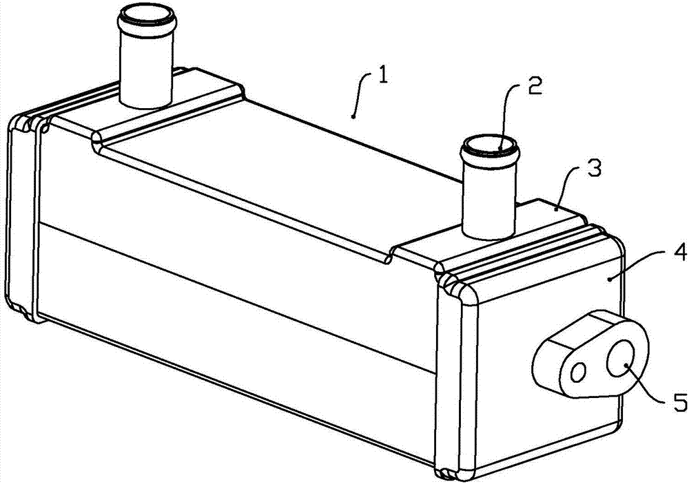
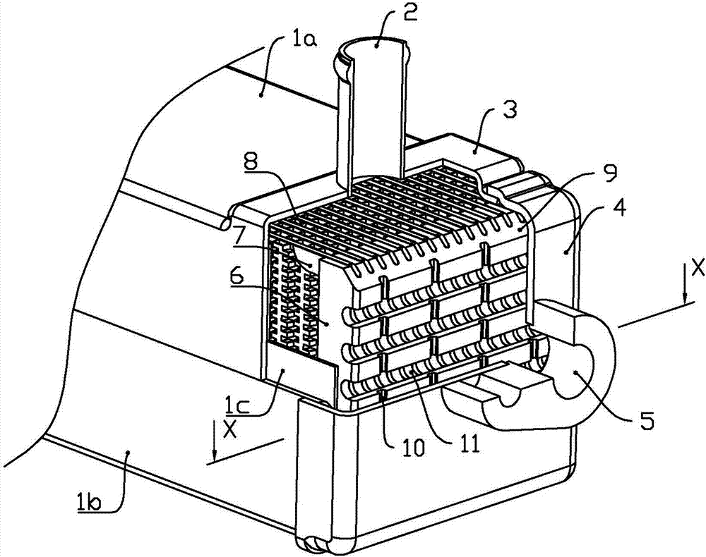
[0027] Below in conjunction with accompanying drawing, the present invention will be further described with specific embodiment, see Figure 1-10 :

[0028] A liquid-cooled heat exchanger for air-conditioning equipment, comprising at least one row of flat tubes 7 and two main boards 6 arranged at both ends of the flat tubes 7, fins 8 are arranged between adjacent flat tubes 7, and the flat tubes 7 and fins 8 The core body of the cooler is formed. The flat tube 7 is inserted into the inner end surface of the main board 6, and the outer end surface of the main board 6 is distributed with a main flow channel 11 and an auxiliary flow channel 10 which are intersected and communicated with each other. The main flow channel 11 and the auxiliary flow channel 10 will The outer end surface of the main board 6 is divided into several small planes, and the main board 6 is provided with a collecting channel 12 connecting the flat tube 7 and the main flow channel 11; The small plane of the...


PUM


Abstract

A liquid cold and hot exchanger for an air-conditioning device comprises at least one line of flat pipes and two main boards arranged at the two ends of the flat pipes. A fin is arranged between every two adjacent flat pipes, and the flat pipes are arranged on the inner end surfaces of the main boards in an inserted mode; main flow passes and auxiliary flow passes are distributed in the outer side surfaces of the main boards, wherein the main flow passes and the auxiliary flow passes are formed in a crossed mode and communicate with each other; the main flow passes and the auxiliary flow passes divide the outer side surfaces of the main boards into a plurality of small panels, the main boards are fixed in a first shell provided with an installation cavity, and the small panels of the outer side surfaces of the main boards are attached to the bottom wall of the installation cavity of the first shell in a brazing mode; a first fluid interface is formed in the outer wall of the first shell, and the first fluid interface, the auxiliary flow passes, flow collecting channels and the plat pipes form a first fluid space; and a second shell is arranged on a core body in a surrounding mode in the circumferential direction, a second fluid interface is formed in the outer wall of the second shell, and the second fluid interface and the fins form a second fluid space. According to the liquid cold and hot exchanger for the air-conditioning device, the small panels are adopted to be attached to the heat exchanger shells in a welding mode, and therefore the anti-pressure capability of the heat exchanger is effectively enhanced.

Description

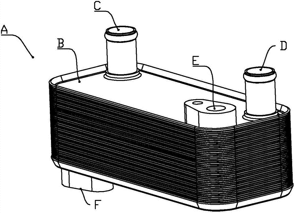
technical field [0001] The invention belongs to the technical field of heat exchangers, in particular to a heat exchanger in an air-conditioning system with a CO2 refrigerant cycle, in particular to a liquid-cooled heat exchanger for air-conditioning equipment. Background technique [0002] Traditional air conditioning systems use R134a. The structure of its liquid-cooled heat exchanger is as follows: figure 1 shown. In the figure, A is the liquid-cooled heat exchanger, B is the core of the liquid-cooled cooler, C is the inlet of the coolant, D is the outlet of the coolant, E is the inlet of the refrigerant, and F is the outlet of the refrigerant. However, due to the high GWP (Global Warming Potential) of R134a, the European Union, the United States and other countries will gradually ban the use of R134a refrigerant in the next few years. The working pressure of the liquid-cooled heat exchanger structure used in traditional air-conditioning equipment is 1.4-2MPa, and the ...

Claims


Application Information

Patent Timeline
IPC IPC(8): F25B39/00F28F9/00
CPCF25B39/00F28F9/00
Inventor 丁天毅谢建
Owner ZHEJIANG YINLUN MACHINERY
Learn More