Wax removal method for crude oil well

A technology for oil wells and crude oil, applied in the field of wax removal, can solve the problems of reduced circulation channels of crude oil, blockage of oil pipes, high wax content, etc., and achieve the effect of easy collection

Inactive Publication Date: 2017-09-05
SICHUAN XILIN OIL SUPPLIES EQUIP
View PDF9 Cites 0 Cited by
  • Summary
  • Abstract
  • Description
  • Claims
  • Application Information

AI Technical Summary

Problems solved by technology

[0006] The purpose of the present invention is to provide a wax removal method for crude oil wells, to solve the problems of wax deposition in oil wells due to the high wax content of crude oil in some places, resulting in reduced crude oil circulation channels, increased oil pressure, and blocked oil pipes

Method used


Image

  • Wax removal method for crude oil well
  • Wax removal method for crude oil well
  • Wax removal method for crude oil well

Examples


Embodiment 1

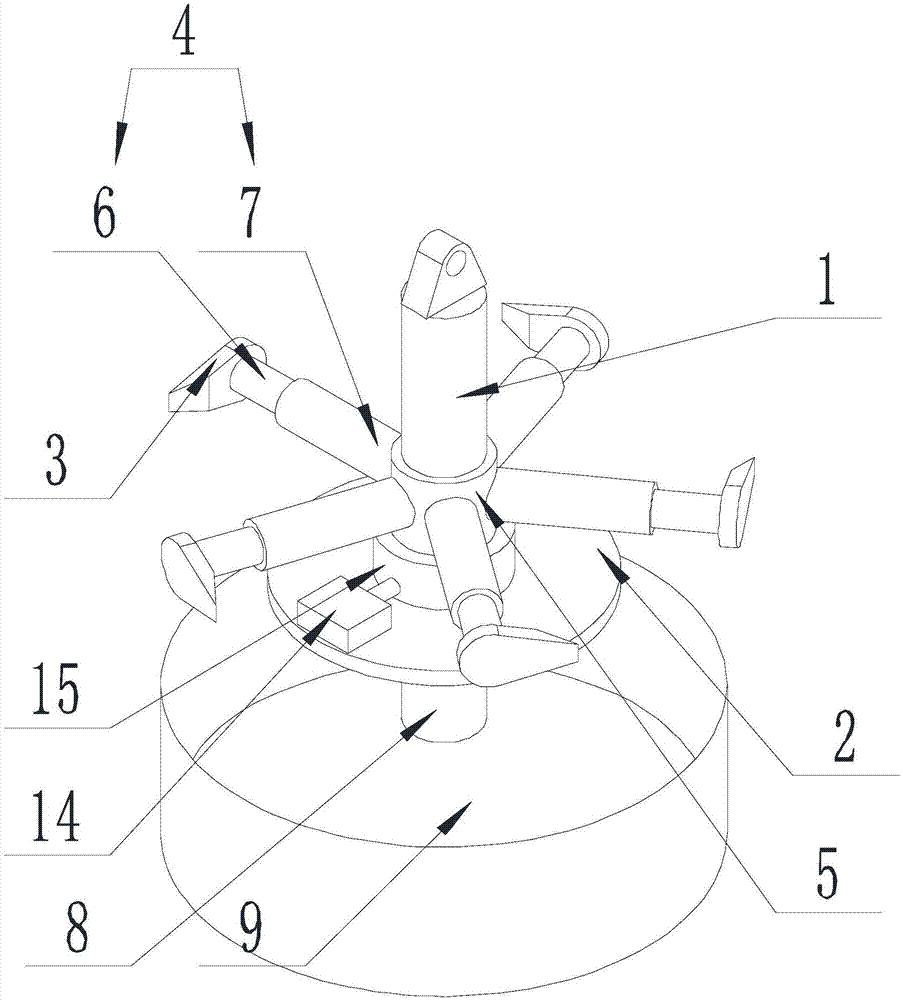
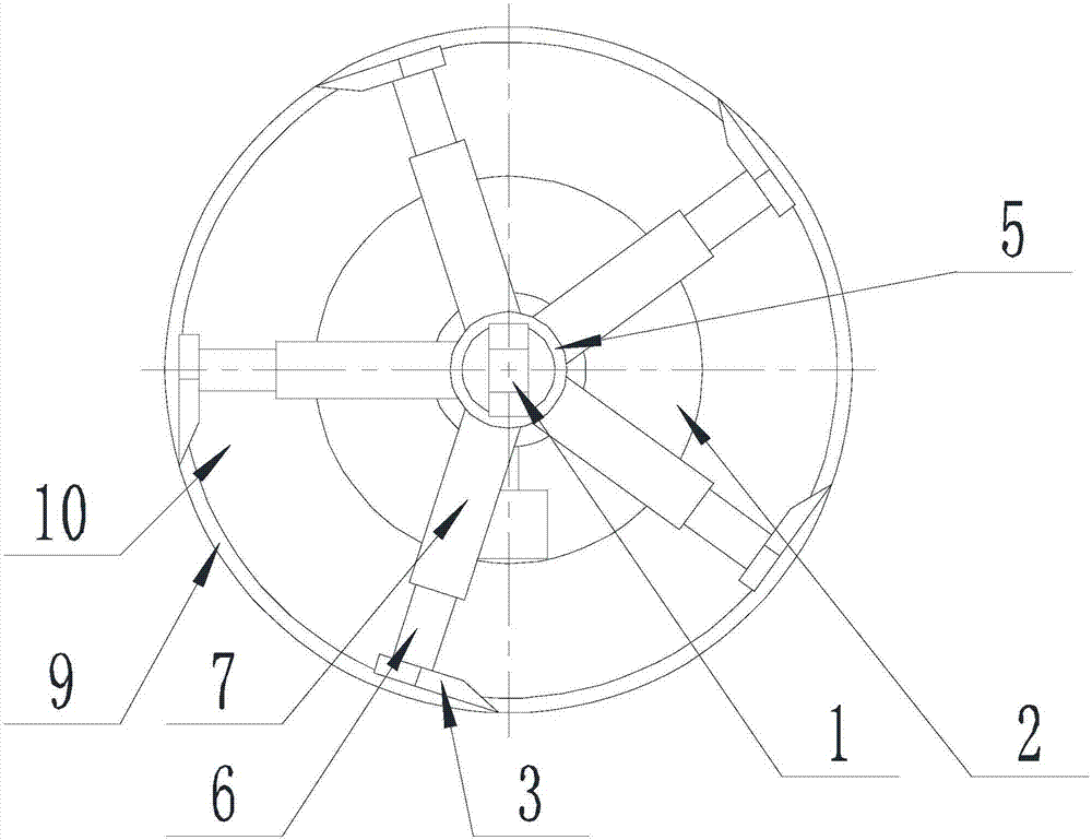
[0033] Such as Figure 1-Figure 4 Shown, the present invention is used for the wax removal method of crude oil well, comprises the steps:

[0034] Step A installation: fix the winch 11 next to the oil well, fix the fixed wheel 13 above the oil well inlet, connect one end of the wire rope 12 to the winch 11, and connect the other end of the wire rope 12 to one end of the connecting shaft 1 after bypassing the fixed wheel 13;

[0035] Step B wax scraping: start the winch 11, lengthen the wire rope 12, so that the wax removal assembly falls along the diameter of the oil well;

[0036] Simultaneously start the driving device, make the scraper assembly go around the connecting shaft 1, and scrape off the wax layer on the well wall;

[0037] Step C Exit: Start the winch 11, shorten the wire rope 12, and withdraw the wax removal assembly from the oil well.

[0038] Put the wax removal assembly into the oil well that needs wax removal through the winch 11 and other devices, and then...

Embodiment 2

[0040] The present invention is based on embodiment 1, and the present invention is further described.

[0041] Such as Figure 1-Figure 4 As shown, the oil well dewaxing device for oil drilling of the present invention, the dewaxing assembly includes a connecting shaft 1, a support plate 2, a scraper assembly and a driving device, one end of the connecting shaft 1 is connected to the suspension device, and the connecting shaft 1 The other end is connected with the support plate 2, the drive device is located on the upper surface of the support plate 2, and connected with the scraper assembly, the drive device drives the scraper assembly to rotate along the axis of the connecting shaft 1.

[0042] Further, the scraper assembly includes a connected scraper 3, a connecting rod 4 and a drum 5, one end of the connecting rod 4 is connected to the scraper 3, the blade of the scraper 3 is parallel to the axis of the drum 5, and the connection The other end of the rod 4 is connected ...

Embodiment 3

[0048] The present invention further explains the drive device on the basis of Embodiment 1.

[0049] Such as Figure 1-Figure 4 As shown, the oil well wax removal device for oil drilling of the present invention, the drive device includes a motor 14 and a gear 15, the motor 14 drives the gear 15 to rotate through a reducer, and the gear is sleeved on the drum 5 and drives Drum 5 rotates.


PUM


Abstract

The invention discloses a wax removal method for a crude oil well. The wax removal method comprises the following steps of (A) fixing a winch next to the oil well, fixing a fixed wheel at the upper part of an oil well inlet, connecting one end of a wire rope and the winch, and connecting the other end of the wire rope and one end of a connection shaft after bypassing the fixed wheel; (B) starting the winch, lengthening the wire rope to make a wax removal assembly fall off along the diameter of the oil well, simultaneously starting a drive device, making a scraper assembly rotate around the connection shaft, and scraping a wax layer on the well wall; and (C) starting the winch, shortening the wire rope, and making the wax removal assembly drop out of the oil well. The wax removal assembly is put into the oil well requiring wax removal through the devices, such as the winch, and the wax on the wall of the oil well is scraped by a scraper blade in the scraper assembly, so that the negative conditions, such as crude oil circulation channel reduction, oil pressure rise and oil pipe blockage, are avoided to ensure smooth normal crude oil circulation and crude oil exploitation.

Description

technical field [0001] The invention relates to a wax removal method, in particular to a wax removal method for crude oil wells. Background technique [0002] Drilling is the project of using mechanical equipment to drill the formation into cylindrical holes with a certain depth. According to the way of rock crushing and the type of tools used, it can be divided into ton drill and rotary drill. [0003] Ton drill, also known as impact drill. The drill bit is sent to the bottom of the well with a wire rope, and the beam mechanism is driven by power, so that one end of the beam moves up and down, and the wire rope and the drill bit are driven to produce an up and down impact to break the rock. The drilling speed of sudden drilling is slow, the efficiency is low, and it cannot adapt to the drilling requirements of increasing well depth and complex formations, and is gradually replaced by rotary drilling. But it has the advantages of simple equipment, low cost, no pollution t...

Claims


Application Information

Patent Timeline
Patent Type & Authority Applications(China)
IPC IPC(8): E21B37/02E21B19/02
CPCE21B37/02E21B19/02
Inventor 贺昶明
Owner SICHUAN XILIN OIL SUPPLIES EQUIP
Why Eureka
Try Eureka