Induced blasting and anti-reflection grouting composite anchor for liquid carbon dioxide

A technology of liquid carbon dioxide and composite bolts, which is applied in the direction of installation of bolts, gas discharge, mining fluids, etc., can solve the problems of increasing the range of surrounding rock fissures, and achieve the effects of expanding the range of fissures, improving the effect, and improving safety

Active Publication Date: 2017-09-05
CENT SOUTH UNIV
View PDF16 Cites 13 Cited by
  • Summary
  • Abstract
  • Description
  • Claims
  • Application Information

AI Technical Summary

Problems solved by technology

[0004] The technical problem to be solved by the present invention is to provide a liquid carbon dioxide blasting anti-reflection grouting that realizes no pollution in the blasting process, adjustable energy, and controllable release mode when reinforcing the above-mentioned surrounding rocks with moderately developed joints and fissures and poor connectivity. Composite bolts to increase the range of cracks in the surrounding rock, expand the diffusion radius of the grout, improve the grouting effect of the surrounding rock, improve and improve the mechanical properties of the surrounding rock, control the deformation of the surrounding rock, and realize the double support function of the bolt and grouting

Method used


Image

  • Induced blasting and anti-reflection grouting composite anchor for liquid carbon dioxide
  • Induced blasting and anti-reflection grouting composite anchor for liquid carbon dioxide
  • Induced blasting and anti-reflection grouting composite anchor for liquid carbon dioxide

Examples


Embodiment Construction

[0024] The present invention will be further described below in conjunction with the accompanying drawings and specific embodiments.

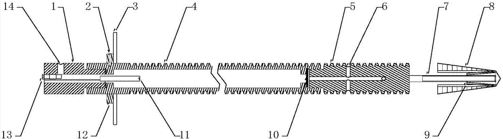
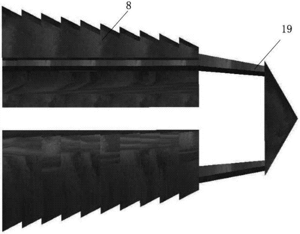
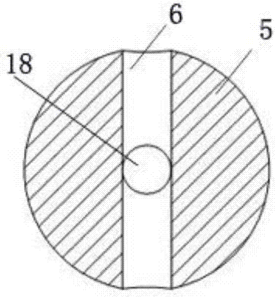
[0025] Such as Figure 1-Figure 5 As shown, a liquid carbon dioxide blasting anti-reflection grouting composite anchor includes an anchor body and an expansion shell anchor head. The anchor body includes a liquid storage pipe 4 and an energy discharge head 5 fixedly connected to the front end of the liquid storage pipe 4 And the filling head 1 that is detachably connected to the rear end of the liquid storage pipe 4, the discharge head 5 is provided with a release pipeline 18 that communicates with the inner cavity of the liquid storage pipe 4, and the outer wall is provided with a drain that passes through the release pipeline. Air holes 6; an energy-dissipating piece 10 is provided between the inner cavity of the liquid storage tube and the release line 18; specifically, the energy-dissipating head 5 rotates in the liquid storage tube 4 and p...


PUM


Abstract

The invention discloses an induced blasting and anti-reflection grouting composite anchor for liquid carbon dioxide. The induced blasting and anti-reflection grouting composite anchor comprises an anchor rod body and an expansion shell anchor head, wherein the anchor rod body comprises a liquid storage tube, an energy release head fixedly connected to the front end of the liquid storage tube, and a filling head detachably connected to the rear end of the liquid storage tube; a release pipe communicating with an inner cavity of the liquid storage tube is arranged in the energy release head; an exhaust hole penetrating through the release pipe is formed in the outer wall; an energy release sheet is arranged between the inner cavity of the liquid storage tube and the release pipe; the expansion shell anchor head is connected to the front end of the energy release head; the filling head is provided with a liquid filling hole communicating with the inner cavity of the liquid storage tube and a valve for controlling the liquid filling hole to open and close; and a heating element is arranged at the rear end of the inner cavity of the liquid storage tube. The fracture is induced through induced blasting of the liquid carbon dioxide, the fracture zone range in a rock mass is effectively expanded, and more favorable conditions are created for executing grouting reinforcement; and meanwhile, grouting reinforcement of the rock mass is executed by directly utilizing a carbon dioxide blast pipe as a grouting channel, so that organic combination of induced blasting and grouting is achieved.

Description

technical field [0001] The invention relates to the technical field of rock and soil reinforcement and support, in particular to a liquid carbon dioxide blasting anti-reflection grouting composite bolt. Background technique [0002] Bolt support is the most economical and effective method to solve stability problems in geotechnical engineering. It has been widely used in various projects such as slope treatment, deep foundation pit support, surrounding rock reinforcement, and structural compression. However, the support and reinforcement of broken rock mass has always been a difficult problem in the field of rock and soil anchoring engineering construction. Especially when the thickness of the broken rock mass exceeds a certain distance, the anchorage section supported by bolts or anchor cables can only act on the broken rock and soil mass. In the middle, the support functions such as suspension and extrusion cannot be formed, effective anchoring cannot be carried out, and t...

Claims


Application Information

Patent Timeline
Patent Type & Authority Applications(China)
IPC IPC(8): E21D21/00E21D20/02E21F7/00E21B43/26E21B33/13
CPCE21B33/13E21B43/26E21D20/003E21D20/02E21D21/0026E21F7/00
Inventor 高峰周科平陈大鹏史文超
Owner CENT SOUTH UNIV
Why Eureka
Try Eureka