Automatic gain control circuit for closed-loop drive of MEMS gyroscope

A technology of automatic gain control and gyroscope, applied in adaptive control, general control system, control/adjustment system, etc., can solve the problem of long start-up time of gyroscope, and achieve less design parameters, simple system, and small start-up time. Effect

Active Publication Date: 2017-09-05
NORTH ELECTRON RES INST ANHUI CO LTD
View PDF5 Cites 15 Cited by
  • Summary
  • Abstract
  • Description
  • Claims
  • Application Information

AI Technical Summary

Problems solved by technology

[0004] In this system, when the gain between DAC input and ADC output is large or the loop bandwidth setting is small, the gain of the automatic gain controller is small, and the output signal of the automatic gain controller is less than full when the gyro starts to vibrate. The swing signal causes the gyro to take a long time to vibrate

Method used


Image

  • Automatic gain control circuit for closed-loop drive of MEMS gyroscope
  • Automatic gain control circuit for closed-loop drive of MEMS gyroscope
  • Automatic gain control circuit for closed-loop drive of MEMS gyroscope

Examples


Embodiment Construction

[0028] The present invention will be further described below in conjunction with the accompanying drawings. The following examples are only used to illustrate the technical solution of the present invention more clearly, but not to limit the protection scope of the present invention.

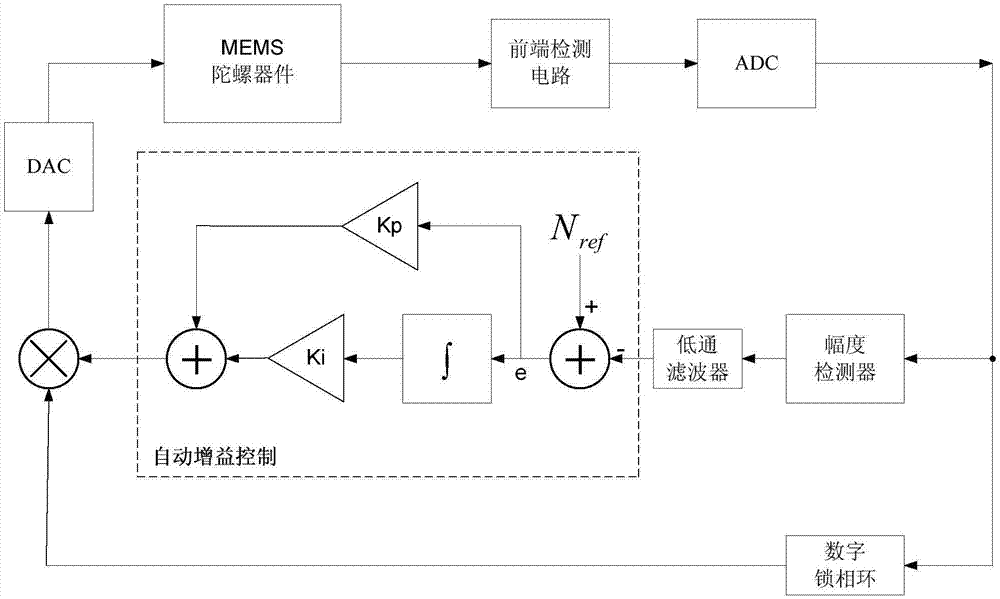
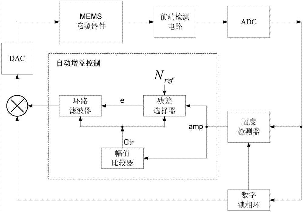
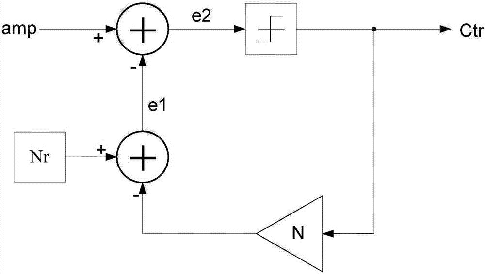
[0029] figure 2 Shown is a schematic diagram of the MEMS gyroscope closed-loop drive based on the automatic gain control circuit of the present invention. The automatic gain control circuit of the present invention, MEMS gyroscope device, front-end detection circuit, analog-to-digital converter (ADC), amplitude detector, digital phase-locked loop, multiplier and digital-to-analog converter (DAC) together constitute a MEMS gyroscope closed-loop driving system. The automatic gain control circuit consists of three parts: loop filter, residual selector and amplitude comparator. where N ref It is a constant for preset digital reference value. The amplitude comparator in the automatic gain contro...


PUM


Abstract

The invention discloses an automatic gain control circuit for closed-loop drive of an MEMS gyroscope. The automatic gain control circuit comprises an amplitude comparator, a residual selector and a loop filter. The amplitude comparator automatically determines whether a gyroscope is in an oscillation starting phase or a stabilizing phase based on the magnitude of an output signal of the amplitude detector, and outputs a control signal for controlling an operation mode of the loop filter and the residual selector according to the determination result. The residual selector outputs an input signal required for the loop filter according to the control signal output from the amplitude comparator and a preset digital reference value. The loop filter generates a drive amplitude signal based on the input signal and the control signal output from the amplitude comparator. The invention designs the amplitude comparator in the automatic gain control circuit to realize the self-detection of a drive system and to adaptively adjust the operation mode of an automatic gain controller; and the oscillation starting time can be less at very small loop bandwidth, the stabilizing time is shorter, meanwhile, fewer design parameters are needed, and the system is more concise.

Description

technical field [0001] The invention relates to an automatic gain control circuit for MEMS gyroscope closed-loop driving. Background technique [0002] With the development of micromachining technology, MEMS silicon micromachined gyroscopes have been widely used in the fields of industrial automation, inertial navigation and automotive electronics. The MEMS gyroscope works on the basis of the Coriolis force principle. According to the Coriolis force formula, it can be known that the driving oscillation rate directly affects the scale factor and stability of the gyroscope. Therefore, maintaining the stability of the gyro driving mode is the key to improving the gyro precision. MEMS gyro drive systems can be divided into open-loop drive and closed-loop drive according to different drive methods. Open-loop drive is easily affected by the external environment, so it can only be used in low-precision fields. The closed-loop drive has strong robustness, can suppress the impact ...

Claims


Application Information

Patent Timeline
Patent Type & Authority Applications(China)
IPC IPC(8): G05B13/04
CPCG05B13/042
Inventor 童紫平贺克军张紫乾吴传奇唐兴刚龙善丽白涛武凤芹王丽
Owner NORTH ELECTRON RES INST ANHUI CO LTD
Why Eureka
Try Eureka