Portable dust remover

A dust collector, a convenient technology, applied in the direction of the coupling device, the device for joining/disconnecting the connecting parts, the parts of the connecting device, etc., can solve the problems of unstable connection, easy to generate arc, uneven plugging force, etc., to achieve Reduce the labor load of personnel, improve the tightness of plug-in connections, and improve work efficiency

Inactive Publication Date: 2017-09-05
南安市申达鑫通商贸有限公司
View PDF5 Cites 4 Cited by
  • Summary
  • Abstract
  • Description
  • Claims
  • Application Information

AI Technical Summary

Problems solved by technology

[0002] With the continuous growth of technologies such as industry, medical technology, and food processing, a large amount of dust and exhaust gas will be generated in the manufacturing process of people. Nowadays, people have gradually strengthened their awareness of air quality improvement. In the manufacturing process, usually use The dust collector cleans the dust and exhaust gas. The dust collector needs electricity during use. The traditional dust collector is usually plugged in manually when it uses electricity, and automatic control operation cannot be realized. Manual plugging by personnel is caused by uneven plugging force. The power head is damaged, and at the same time, it is easy to generate an electric arc when plugging and unplugging, which leads to electric shock accidents, which poses a great safety hazard. In addition, the traditional manual plugging method also has unstable connections, and the function is single

Method used


Image

  • Portable dust remover
  • Portable dust remover
  • Portable dust remover

Examples


Embodiment Construction

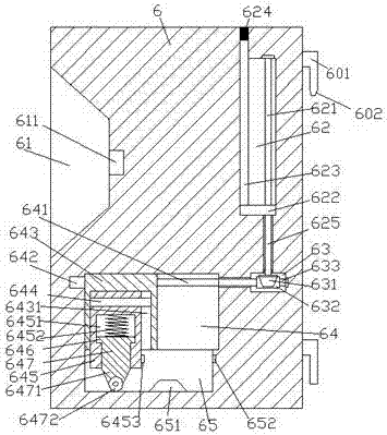
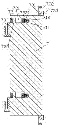
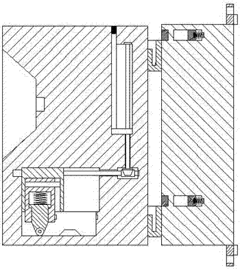
[0026] Such as Figure 1-Figure 8 As shown, a convenient dust collector device of the present invention includes a communication platform 6 and a hanging frame 7, a first sliding chamber 64 is provided in the communication platform 6, and the bottom end of the first sliding chamber 64 is provided with Guide chute 65, the first sliding cavity 64 is provided with a first stud 641 extending left and right, the left end of the first stud 641 is power connected with the first power device 642, and the first stud 641 A first sliding block 643 is threadedly connected to the column 641, and a first slide groove 6431 is arranged inside the first slide block 643, and a guide slide bar 644 extending left and right is arranged inside the first slide groove 6431, so that The guide slide bar 644 is smoothly connected with a second slider 645, and the bottom of the second slider 645 pushes into the guide chute 65 and is connected smoothly. The second slider 645 is provided with a first Two ...


PUM


Abstract

The invention discloses a portable dust remover, and the dust remover comprises a power-on platform and a hanging rack. The interior of the power-on platform is provided with a first sliding cavity, and the internal bottom of the first sliding cavity is provided with a guide chute. The interior of the first sliding cavity is provided with a first stud which is extended laterally. The left side end of the first stud is in power connection with a first power unit, and the first stud is in screw-thread fit connection with a first sliding block. The interior of the first sliding block is provided with a first chute. The interior of the first chute is provided with a guide sliding rod which extends laterally. The guide sliding rod is in smooth fit connection with a second sliding block, and the bottom of the second sliding blocks is pushed into the guide chute and achieves the smooth fit connection. The interior of the second sliding block is provided with a second sliding cavity, and the interior of the second sliding cavity is provided with a third sliding block. The bottom of the third sliding block is provided with a first elastic piece, and is also provided with a press sliding block which passes through the bottom end face of the second sliding block. The bottom of the press sliding block is provided with a connection segment, and the bottom of the connection segment is provided with a rotating wheel. The dust remover is simple in structure, is convenient to operate, can achieve the operation and power supply plugging, is convenient for installation and disassembly, and is high in safety.

Description

technical field [0001] The invention relates to the technical field of dust collectors, in particular to a convenient dust collector device. Background technique [0002] With the continuous growth of technologies such as industry, medical technology, and food processing, a large amount of dust, exhaust gas, etc. will be generated in the manufacturing process of people. Nowadays, people have gradually strengthened their awareness of air quality improvement. In the manufacturing process, usually use The dust collector cleans the dust and exhaust gas. The dust collector needs electricity during use. The traditional dust collector is usually plugged in manually when it uses electricity, and automatic control operation cannot be realized. Manual plugging by personnel is caused by uneven plugging force. The electric head is damaged, and at the same time, it is easy to generate an electric arc when plugging and unplugging, which leads to electric shock accidents, which has great p...

Claims


Application Information

Patent Timeline
Patent Type & Authority Applications(China)
IPC IPC(8): H01R13/62H01R13/629
CPCH01R13/6205H01R13/629
Inventor 叶棋刚
Owner 南安市申达鑫通商贸有限公司
Why Eureka
Try Eureka