
Decoupled current droop control method of shunt chopper in microgrid

A control method and inverter technology, applied in the direction of single-network parallel feeding arrangement, etc., can solve problems such as poor practical feasibility, noise interference, and no improvement in dynamic response, and achieve good system stability, fast dynamic response, The effect of maintaining redundancy

Active Publication Date: 2017-09-05
XI AN JIAOTONG UNIV
View PDF3 Cites 5 Cited by
  • Summary
  • Abstract
  • Description
  • Claims
  • Application Information

AI Technical Summary

Problems solved by technology

Some literature proposes to use communication lines to share the current, but although this method realizes the current sharing among multiple inverters, the use of communication lines increases the cost and is also susceptible to noise interference.
There are also literatures that use a current resonator to control the current peak value. Although this method can also achieve accurate current sharing, this method requires real-time adjustment of the resonant frequency of the resonant controller, which does not improve the dynamic response of the system.
Recently, there are also literatures that use the intrinsic droop mechanism between the direct-axis component and quadrature-axis component of the output current and the amplitude and phase of the voltage to propose a new current droop control strategy. However, this method requires each inverter to have similar hardware. Parameter and controller parameter design, practical feasibility is not strong
There are also literatures that establish a drooping relationship between voltage and current in the synchronous rotating coordinate system to achieve current sharing. However, the synchronization mechanism of this method is based on the structure of master-slave control, which will reduce the redundancy of system operation.

Method used


Image

  • Decoupled current droop control method of shunt chopper in microgrid
  • Decoupled current droop control method of shunt chopper in microgrid
  • Decoupled current droop control method of shunt chopper in microgrid

Examples


Embodiment Construction

[0044] The present invention will be further described in detail below in conjunction with specific embodiments, which are explanations of the present invention rather than limitations.

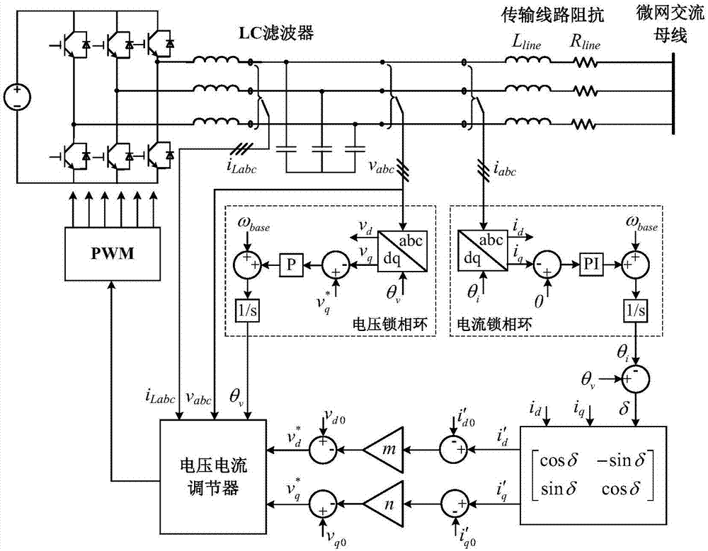
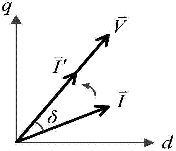
[0045] refer to figure 1 with figure 2 , the present invention proposes a decoupling current droop control method for parallel inverters in a microgrid, aiming to solve the problems of current sharing effect, dynamic response and system stability of traditional droop control inverters.

[0046] Its specific implementation steps are as follows:

[0047] 1) In an AC microgrid, there are N parallel inverters, and each inverter is controlled as a voltage source according to the same current droop control strategy.

[0048] 2) Each inverter collects the phase information of the voltage at both ends of the capacitor through the voltage phase-locked loop, obtains the direct-axis component and the quadrature-axis component of the voltage vector, and generates a reference value of the voltage frequ...


PUM


Abstract

The invention discloses a decoupled current droop control method of a shunt chopper in a microgrid, and belongs to the field of coordination control of the shunt chopper in the microgrid. Different from traditional droop control, according to the method, there is no need to calculate output power of inverters, a virtual current vector having the same phase position with a voltage vector is generated by conducting rotation transformation on a current vector, and accordingly a droop relationship between the voltage and the virtual current is built under a synchronous rotating reference frame. By designing parameters reasonably, the droop relationship can naturally form control characteristics of virtual impedance to compensate decrease of the current equipartition effect caused by difference of line impedance. Besides, a voltage phase-locked loop based on a proportional regulator is adopted for generating a reference value of a voltage frequency, and compared with a traditional phase-locked loop based on a proportional-integral regulator, the phase-locked loop in the method can ensure that the shunt chopper is operated synchronously with an equal status, and maintain the redundancy. According to the decoupled current droop control method of the shunt chopper in the microgrid, the precise equipartition of a load current among inverters can be achieved.

Description

technical field [0001] The invention belongs to the field of coordinated control of parallel inverters in a microgrid, and in particular relates to a decoupling current droop control method for parallel inverters in a microgrid. Background technique [0002] With the deepening of environmental and energy crisis, the concept of microgrid has received more and more attention and application. A microgrid is an energy system that combines distributed power sources and interconnected loads. In most cases, the microgrid is connected to the busbar through a power electronic interface, such as an inverter. Therefore, the coordinated control among parallel inverters is one of the key factors for the stable and efficient operation of the microgrid. [0003] Due to the geographical dispersion of distributed power supplies, it is often not feasible to use communication lines to transmit signals between parallel power supplies, because this will increase costs and reduce system reliabi...

Claims


Application Information

Patent Timeline
IPC IPC(8): H02J3/38
CPCH02J3/38
Inventor 刘进军武腾刘增安荣汇刘宝谨
Owner XI AN JIAOTONG UNIV
Learn More