
Uniform-temperature heat dissipation device comprising cold plate array for power battery pack and processing method of heat dissipation device

A technology of a heat dissipation device and a cold plate, which is applied to the field of heat dissipation and cooling devices for battery packs, can solve the problems of loose battery arrangement, increase the volume of the heat sink, and uneven cooling air, so as to improve the heat dissipation effect, strengthen the heat dissipation effect, and increase the heat dissipation area. Effect

Pending Publication Date: 2017-09-08
NANJING FORESTRY UNIV
View PDF6 Cites 8 Cited by
  • Summary
  • Abstract
  • Description
  • Claims
  • Application Information

AI Technical Summary

Problems solved by technology

However, like the traditional air-cooled radiator, it does not solve the problem of the small heat dissipation area of ​​the battery pack; although the air diameter of the radiator without deflectors has been improved, the cooling air is still uneven; and in order to ensure the heat dissipation effect, The arrangement of the batteries is relatively loose, which increases the volume of the radiator

Method used


Image

  • Uniform-temperature heat dissipation device comprising cold plate array for power battery pack and processing method of heat dissipation device
  • Uniform-temperature heat dissipation device comprising cold plate array for power battery pack and processing method of heat dissipation device
  • Uniform-temperature heat dissipation device comprising cold plate array for power battery pack and processing method of heat dissipation device

Examples


Embodiment Construction

[0036] In order to make the purpose, technical solution and advantages of the present invention clearer, the present invention will be further described in detail below in conjunction with the accompanying drawings and examples of implementation. It should be understood that the specific implementation cases described here are only used to explain the present invention, not to limit the present invention.

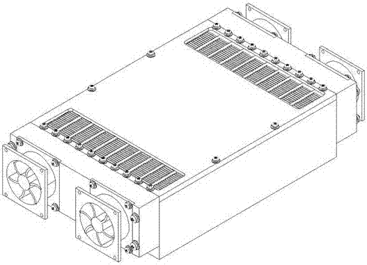
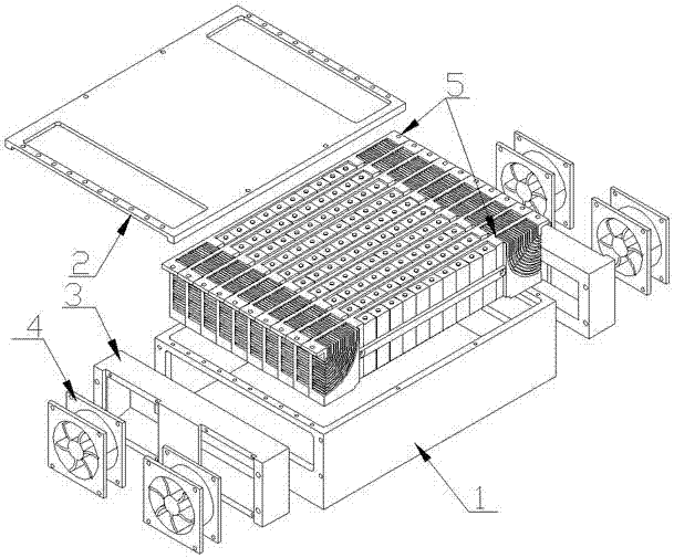
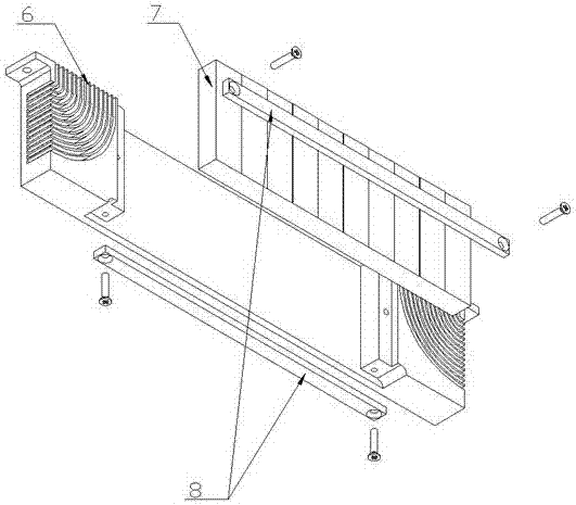
[0037] Such as figure 1 , figure 2 As shown, the example of the present invention includes a radiator housing 1 , a cold plate cooling array 5 , an upper cover 2 , a fan shroud 3 and a fan 5 . The cold plate heat dissipation array 5 is composed of several cold plate heat dissipation components arranged side by side. The cold plate cooling assembly includes a cold plate 6 , a battery pack 7 , and a fixing bar 8 . Such as Figure 8 As shown, the flat-head screws pass through the fixing bar 8 to fix the battery pack 7 and the cold plate 6 as a whole.

[0038] The cold pl...


PUM


Abstract

The invention discloses a uniform-temperature heat dissipation device comprising a cold plate array for a power battery pack. The heat dissipation device comprises a heat sink shell, the cold plate array, an upper cover plate, a fan diversion cover and a fan, wherein the cold plate array comprises a plurality of heat dissipation assemblies in parallel, each heat dissipation assembly comprises a cold plate, a battery pack and a fixing strip, fin groups are processed at two ends of the cold plate, a heat pipe is packaged in a back plate of the cold plate and extends to bottom parts of the fin groups all the way, air inlets are formed in two surfaces of the heat sink shell, the plurality of heat dissipation assemblies are placed in the shell to form a heat dissipation array, the fan diversion cover is arranged outside the heat sink shell, a diversion cavity with a trapezoid cross section is arranged in the fan diversion cover, a relatively small end is flush with the air inlets, and the fan is arranged at a relatively large end. By the technical scheme, heat generated by a power battery pack of a new energy automobile during charging and discharging can be efficiently taken away on the condition of maintaining favorable temperature uniformity, so that reliable working of the automobile battery is maintained under a relatively good working temperature. The invention also provides a processing method of the heat dissipation device.

Description

technical field [0001] The invention relates to a heat dissipation and cooling device for a battery pack, in particular to a high-efficiency uniform temperature heat dissipation device for a power pack of a new energy vehicle. Background technique [0002] With the development of science and technology, the concept of environmental protection has gradually become popular among the people. In order to control the use of fossil fuels and reduce exhaust emissions, traditional internal combustion engine vehicles are restricted by many regulations. Relatively electric vehicles and hybrid vehicles have gradually been favored by people. The battery pack is one of the core components of electric vehicles and hybrid vehicles. Its performance directly affects the performance of the vehicle, and the performance and life of the battery are closely related to its working temperature. The battery pack will generate heat during charging and discharging, which will increase the overall tem...

Claims


Application Information

Patent Timeline
IPC IPC(8): H01M10/613H01M10/625H01M10/6551H01M10/6552H01M10/6554H01M10/6555H01M10/6563
CPCH01M10/613H01M10/625H01M10/6551H01M10/6552H01M10/6554H01M10/6555H01M10/6563H01M2220/20Y02E60/10
Inventor 马哲树侯小宇陈苏蓉姚禹缪旭张涌
Owner NANJING FORESTRY UNIV
Features
  • Generate Ideas
  • Intellectual Property
  • Life Sciences
  • Materials
  • Tech Scout
  • Unparalleled Data Quality
  • Higher Quality Content
  • 60% Fewer Hallucinations
Learn More