Flue gas dust collector

A dust collector and flue gas technology, applied in chemical instruments and methods, using liquid separation agents, separation devices, etc., can solve the problems of unsatisfactory filtration effect, low recycling rate, high cost, etc., and achieve improved dust removal effect, High dust removal efficiency and simple structure

Pending Publication Date: 2017-09-12
湖州博通节能环保设备有限公司
View PDF6 Cites 5 Cited by
  • Summary
  • Abstract
  • Description
  • Claims
  • Application Information

AI Technical Summary

Problems solved by technology

If the dust removal effect is not good, it will affect the quality of the product, and it will also cause irreversible damage to the body of workers in this working environment for a long time
At present, there are three types of dust removal equipment: electrostatic precipitator, bag filter, and inertial dust collector. Each type of equipment has its own limitations, and most of the existing dust removal equipment has complex structures and expensive manufacturing costs, and the filtering effect is also low. not ideal
Chinese Patent No. CN201621133125.2, the patent name is "A High-Efficiency Flue Gas Dust Collector", although it solves the above problems to a certain extent, its disadvantage is that the degree of fusion between flue gas and water is not enough, resulting in relatively high impurities in the flue gas. In addition, the structural design is unreasonable, the water recycling rate is low, water resources are wasted, and the cost is high.

Method used


Image

  • Flue gas dust collector
  • Flue gas dust collector

Examples


Embodiment 1

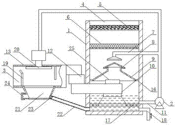
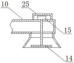
[0015] A kind of flue gas deduster of the present invention is made up of spray tower 1, pump body 2, air inlet 3 and air outlet 4, and the top of its described spray tower 1 is air outlet 4, and inside spray tower 1 The cavity is provided with a first activated carbon layer 5, a second activated carbon layer 6, a spray pipe 7, a liquid cap 8, a diversion cover 9 and an air inlet pipe 10 in sequence from top to bottom, and the lower part of the spray tower 1 is provided with a liquid outlet pipe. 11 communicates with the inlet of the pump body 2, the inlet end of the air intake pipe 10 is connected with the blower fan 12 and the primary spray box 13 in turn, the other end of the primary spray box 13 is the air inlet 3, and the outlet pipeline of the pump body 2 is connected with the The spray pipe 7 is connected, and the end of the spray pipe 7 is equipped with a mist distributor 14, and the other outlet pipeline of the pump body 2 is connected with the primary spray tank 13, a...

Embodiment 2

[0017] A kind of flue gas deduster of the present invention is made up of spray tower 1, pump body 2, air inlet 3 and air outlet 4, and the top of its described spray tower 1 is air outlet 4, and inside spray tower 1 The cavity is provided with a first activated carbon layer 5, a second activated carbon layer 6, a spray pipe 7, a liquid cap 8, a diversion cover 9 and an air inlet pipe 10 in sequence from top to bottom, and the lower part of the spray tower 1 is provided with a liquid outlet pipe. 11 communicates with the inlet of the pump body 2, the inlet end of the air intake pipe 10 is connected with the blower fan 12 and the primary spray box 13 in turn, the other end of the primary spray box 13 is the air inlet 3, and the outlet pipeline of the pump body 2 is connected with the The spray pipe 7 is connected, and the end of the spray pipe 7 is equipped with a mist distributor 14, and the other outlet pipeline of the pump body 2 is connected with the primary spray tank 13, a...


PUM


Abstract

The invention discloses a flue gas dust collector and belongs to the field of chemical equipment. The flue gas dust collector comprises a spraying tower, a pump body, an air inlet and an air outlet; the top of the spraying tower is the air outlet; an inner cavity of the spraying tower is sequentially provided with a first activated carbon layer, a second activated carbon layer, a spraying pipe, a liquid cap, a diversion cover and an air inlet pipeline from top to bottom; the lower part of the spraying tower is provided with a liquid outlet pipe to be communicated with an inlet of the pump body; the inlet end of the air inlet pipeline is sequentially communicated with a fan and a primary spraying box; the other end of the primary spraying box is the air inlet; one path of an outlet pipeline of the pump body is communicated with the spraying pipe; a fog distributor is installed at the end part of the spraying pipe; and the other path of the outlet pipeline of the pump body is communicated with the primary spraying box. The flue gas dust collector has a simple structure and is convenient to operate and high in dust collection efficiency. By adopting the flue gas dust collector, corresponding substances are moved from flue gas after the flue gas passes through a primary dust collection box and dust collection liquid in a tower body, so that the dust collection effect is greatly improved, wherein water in the whole device is recycled, so that the effects of water conservation and cost reduction are facilitated.

Description

technical field [0001] The invention belongs to the field of chemical equipment, in particular to a flue gas dust collector. Background technique [0002] A large amount of dust will be generated in the production of recycled synthetic chemical products, for example, there will be a large amount of suspended particles in the smoke generated during the chemical reaction process of producing PVDC latex. If the dust removal effect is not good, it will affect the quality of the product, and it will also cause irreversible damage to the health of workers in this working environment for a long time. At present, there are three types of dust removal equipment: electrostatic precipitator, bag filter, and inertial dust collector. Each type of equipment has its own limitations, and most of the existing dust removal equipment is complex in structure and expensive to manufacture, and the filtering effect is also low. not ideal. Chinese Patent No. CN201621133125.2, the patent name is "...

Claims


Application Information

Patent Timeline
Patent Type & Authority Applications(China)
IPC IPC(8): B01D47/06B01D47/02
CPCB01D47/06B01D2247/10B01D2247/04
Inventor 王万垒司学强
Owner 湖州博通节能环保设备有限公司
Why Eureka
Try Eureka