A guide roller and guide roller assembly tooling

A technology for assembling tooling and guide rollers. It is used in guiding/positioning/aligning devices, manufacturing tools, metal processing and other directions. It can solve problems such as difficulty, inconvenience in replenishing lubricating oil, and deformation of oil injection holes to ensure service life. , to avoid adverse effects, to supplement the effect of sufficient lubrication

Active Publication Date: 2019-02-12
YONGXING SPECIAL STAINLESS STEEL
View PDF7 Cites 0 Cited by
  • Summary
  • Abstract
  • Description
  • Claims
  • Application Information

AI Technical Summary

Problems solved by technology

An important reason for the failure of the guide roller is that the lubrication performance of the guide roller is poor, or it is inconvenient to replenish lubricating oil, and the effect of relubrication is not good, which leads to premature dry friction of the guide roller and accelerates the damage of the guide roller; another important reason for the failure of the guide roller The reason is that the bearings in the guide rollers are under uneven force, causing the bearing on one side of the guide roller to fail first due to the greater force, or the two guide rollers at the same position are under uneven force, resulting in a larger guide roller on one side of the wire. The faster one fails first, and more of these two situations occur at the same time
[0003] The existing guide rollers with bearings are often processed with oil injection holes inside the guide roller body, and the outer surface is installed with an oil injection nozzle to add oil. However, oil injection through the oil injection holes will lead to many and difficult processing procedures for the guide roller body, and increase the cost of the guide roller body. The processing cost, and the uneven distribution of the mass of the guide roller in the circumferential direction, produces an unbalanced moment of inertia when the guide roller is running. Although the uneven distribution of the circumferential mass is relatively light, due to the high temperature, high stress and high intensity Under the environment, the existence of the moment of inertia will aggravate the deformation of the accelerated parts. The first thing to bear the brunt is that the deformation of the oil injection hole area will be aggravated. The size of the oil injection hole itself is also affected by the deformation, which makes it difficult to ensure the quality of lubrication; , the installation of the bearings is often done by hand one by one, it is difficult to ensure the degree of stress and concentricity of the bearings on both sides of the same guide roller after installation, further, the installation conditions of the two guide rollers that cooperate with each other at the same position The state is also different, and it is easy to cause uneven force on the inside of the guide roller or on the two guide rollers at the same position

Method used


Image

  • A guide roller and guide roller assembly tooling
  • A guide roller and guide roller assembly tooling
  • A guide roller and guide roller assembly tooling

Examples


Embodiment 1

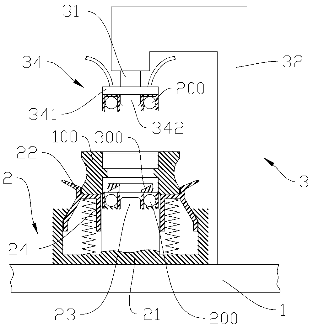
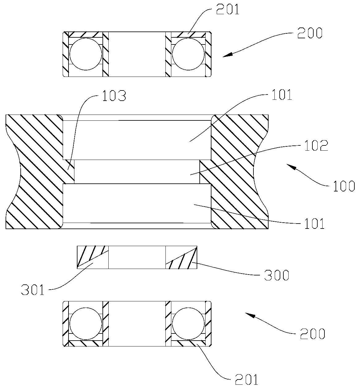
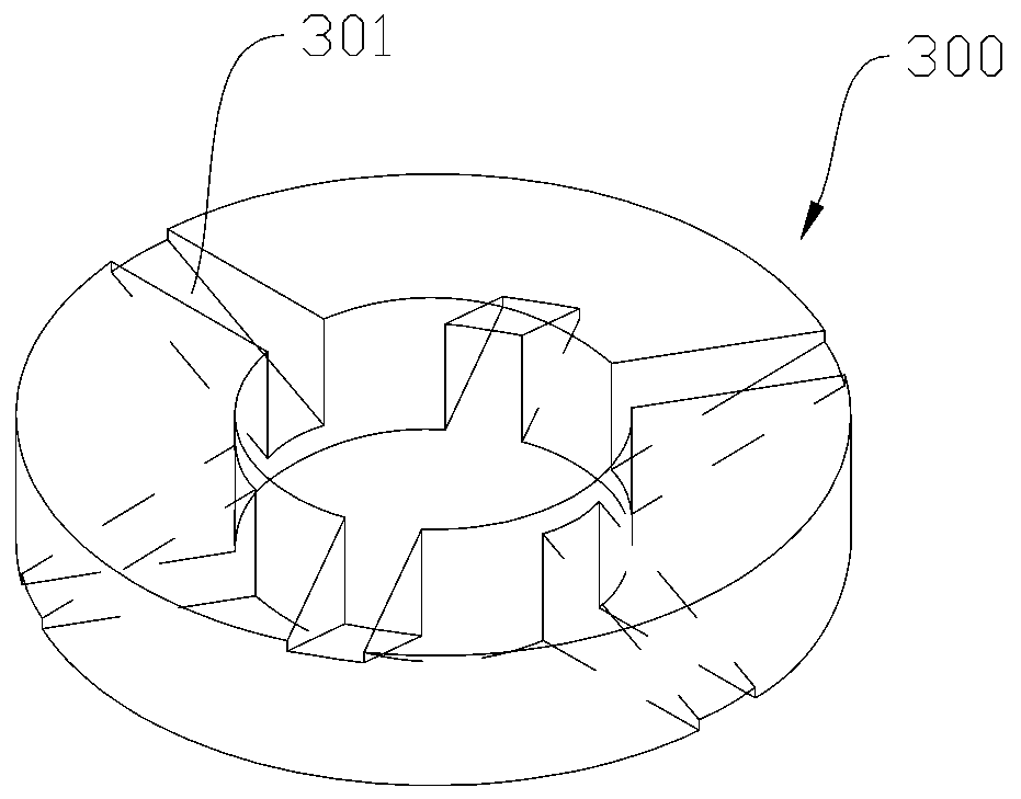
[0031] Embodiment 1: as Figure 1-4 Shown, a kind of guide roller, comprises guide roller body 100, a pair of bearings 200 that set up the upper and lower end faces of guide roller body 100 separately, the oil separator 300 that is installed between bearing 200; The bearing mounting hole 101 of the bearing 200 and the oil separating hole 102 for accommodating the oil separating plate 300 are opened between the bearing mounting hole 101; The end faces covered with the sealing cover are installed facing each other. The outer diameter of the bearing 200 is interference fit with the bearing installation hole 101, and the oil separator 300 is in clearance fit with the oil distribution hole 102. After the guide roller is assembled, the sealing covers 201 on the upper and lower end surfaces of the guide roller body 100 on the two bearings are sealed. It covers the upper and lower end surfaces of the guide roller body 100 to prevent the lubricating grease in the bearing 200 from seep...

Embodiment 2

[0044] Such as Figure 6 As shown, a pair of material platforms can be arranged on the bottom platform, and a pair of pressing heads matching the material platforms can be arranged on the pressing member. In this way, the assembly of two guide rollers is completed at one time, and the two guide rollers are assembled at the same time, and the two guide rollers are used at the same position, which effectively improves the force consistency of the two guide rollers and improves the running stability of the guide rollers, thereby Guarantee and prolong the service life of the guide roller.


PUM


Abstract

The invention discloses a guide roll. The guide roll comprises a guide roll body, a pair of bearings which are separately arranged on the upper and lower end surfaces of the guide roll body and an oil distribution sheet arranged between the bearings, wherein the upper end lower bottom surfaces of the guide roll body are separately provided with a bearing assembly hole used for accommodating the bearings; an oil distribution hole for accommodating the oil distribution sheet is formed between the bearing assembly holes; and only one end surface of each bearing is covered with a sealing cover. The invention further discloses a guide roll assembly fixture which comprises a base arranged on an ordinary worktable, a material table which is arranged on the base and is used for sequentially placing guide roll parts to be assembled and a compaction device which is fixedly connected to the base and is used for assembling the guide roll parts which are sequentially placed. According to the guide roll, a lubricant supplement problem of the guide roll is ingeniously solved due to the structure of the guide roll; the two bearings on the same guide roll can be assembled synchronously by the guide roll assembly fixture; and two guide rolls on the same use position can be finished synchronously; and the service life of the guide roll is effectively ensured and prolonged.

Description

technical field [0001] The invention relates to the field of high-speed wire rod rolling in steel rolling production, in particular to a guide roller and a guide roller assembly tool. Background technique [0002] During high-speed wire rolling, the size of the finished wire rod is small and the rolling passes are many, so the rolling speed is high when the rolled piece enters the finishing rolling area. In order to help the rolled piece bite smoothly and improve the surface quality of the wire rod, a pair of guide rollers need to be installed at each entrance of the finishing rolling area. The working conditions of the guide rollers of the finishing mill are very harsh, and they are always in a state of high-speed rotation. The frequencies are larger. Guide rollers with a longer life help to improve product quality and improve the operating efficiency of the production line, reducing the time and frequency of maintenance and replacement parts. An important reason for the...

Claims


Application Information

Patent Timeline
Patent Type & Authority Patents(China)
IPC IPC(8): B21B39/16B21B28/00B21B1/16B23P19/027B23P19/02
CPCB21B1/16B21B28/00B21B39/16B23P19/02B23P19/027
Inventor 彭飞高亦斌金卫强冯惠伟李少正丁淑芳姚亮徐威卢健儿
Owner YONGXING SPECIAL STAINLESS STEEL
Why Eureka
Try Eureka