Vertical drying and screening tower

A vertical and sieve plate technology, applied in drying, drying machine, drying solid materials and other directions, can solve the problems of poor temperature controllability, poor temperature control, high material crushing ratio, low cost, drying Fast speed and small footprint

Inactive Publication Date: 2017-09-12
郭大军
View PDF4 Cites 2 Cited by
  • Summary
  • Abstract
  • Description
  • Claims
  • Application Information

AI Technical Summary

Problems solved by technology

In the traditional vertical drying tower, multiple porous column air distribution pipes are erected in the tower body, and the wet material is vertically used from the top to the bottom at the feed inlet, so that the materials in the middle and lower layers of the tower body bear the pressure of all the materials in the upper layer and reach the material in the tower. High crushing ratio, low yield
Also due to unreasonable structure, crushed materials block ventilation, serious steaming phenomenon, poor temperature controllability, easy to burn and damage equipment accidents, poor drying effect and low production capacity
Because the temperature in the tower is not well controlled, coupled with uneven ventilation, it is often easy to cause the briquettes to catch fire and burn, and the energy consumption in the drying process is relatively high

Method used


Image

  • Vertical drying and screening tower
  • Vertical drying and screening tower

Examples


Embodiment Construction

[0025] Example embodiments will now be described more fully with reference to the accompanying drawings. Example embodiments may, however, be embodied in many forms and should not be construed as limited to the embodiments set forth herein; rather, these embodiments are provided so that this disclosure will be thorough and complete, and will fully convey the concept of example embodiments to those skilled in the art.

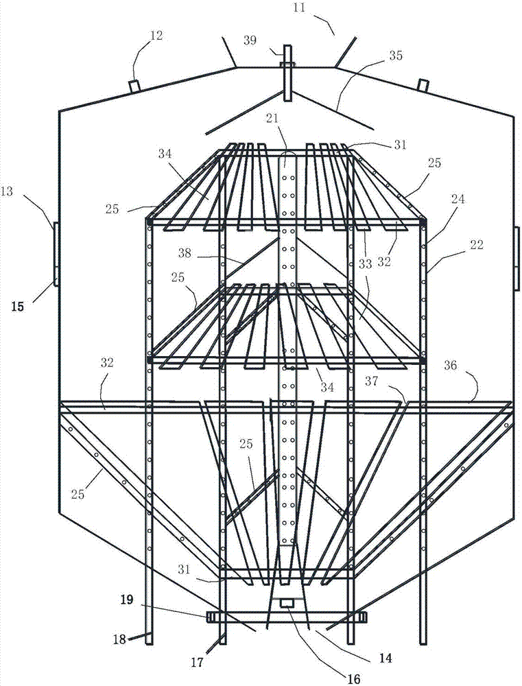
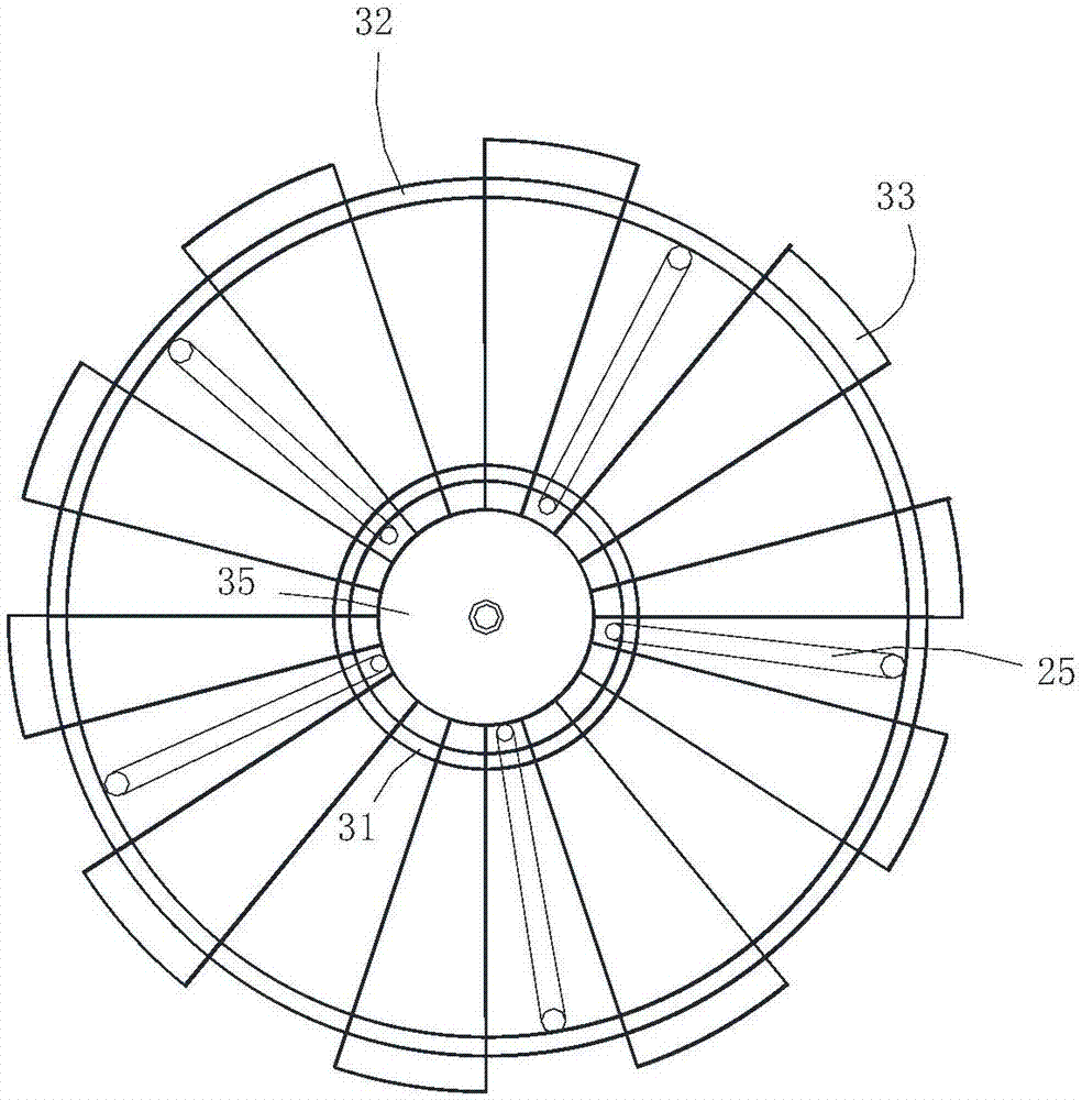
[0026] Such as figure 1 Shown is the structural representation of the neutral vertical drying and screening tower of the present invention; figure 2 Shown is a schematic structural view of the supporting component in the present invention.

[0027] The vertical drying and screening tower adopts grate distribution, drying and screening. Its structure includes: tower body, hot air pipe, sieve plate, and distribution slide plate; The slide plate is arranged above the grate bars.

[0028] The top of the tower is round, the middle is cylindrical, and the bottom ...


PUM


Abstract

The invention discloses a vertical drying and screening tower. The vertical drying and screening tower comprises a tower body, a hot wind pipe, a screen plate and a distribution carriage plate; the hot wind pipe, the screen plate and the distribution carriage plate are arranged in the tower body; the distribution carriage plate is arranged above a grid section; the tower body is provided with a feed port and an exhaust port in the top, and is provided with a discharge port in the bottom; the hot wind pipe comprises a center hot wind pipe, longitudinal hot wind pipes and a hot wind inclined beam; the center hot wind pipe, the longitudinal hot wind pipes and the hot wind inclined beam are provided with hot wind holes; the grid section and the hot wind inclined beam are fixed between an inner ring beam and an outer ring beam; the hot wind inclined beam communicates with the longitudinal hot wind pipes and the center hot wind pipe; multiple longitudinal hot wind pipes are fixed on the inner sides or the outer sides of the inner and outer ring beams; two ends of the longitudinal hot wind pipes are closed; the bottoms of the longitudinal hot wind pipes outwards extend to support on the ground; and the bottoms of the longitudinal hot wind pipes on the inner ring outwards extend to support on the ground through a first hot wind box. The vertical drying and screening tower is uniform in ventilation, high in drying speed and low in cost.

Description

technical field [0001] The invention relates to a drying equipment, in particular to a vertical drying and screening tower. Background technique [0002] The working principle of the traditional vertical drying tower is: input the wet briquette into the tower body, and then pass an appropriate amount of hot air into the tower body, use the hot air to heat and take away the moisture, but the ventilation is uneven, the crushing rate is high, and serious Affects production cost and quality, has a lot of powder and is not environmentally friendly. However, compared with the horizontal chain drying box, the capital investment is small, the operation is simple, the cost is low, and the land occupation is small, so it is widely used. In the traditional vertical drying tower, multiple porous column air distribution pipes are erected in the tower body, and the wet material is vertically used from the top to the bottom at the feed inlet, so that the materials in the middle and lower ...

Claims


Application Information

Patent Timeline
Patent Type & Authority Applications(China)
IPC IPC(8): F26B17/12F26B21/14F26B25/00B07B9/00
CPCF26B17/122F26B21/004F26B21/14F26B25/002B07B9/00
Inventor 郭大军郭宪录
Owner 郭大军
Why Eureka
Try Eureka