Droplet generator and droplet preparation method

A technology of droplet generator and manufacturing method, applied in the direction of instruments, preparation of samples for testing, analysis of materials, etc.

Inactive Publication Date: 2017-09-12
SHANGHAI JIAO TONG UNIV
View PDF10 Cites 8 Cited by
  • Summary
  • Abstract
  • Description
  • Claims
  • Application Information

AI Technical Summary

Problems solved by technology

This droplet generator is mainly used in inkjet printer nozzles and cannot be applied under extreme environmental conditions

Method used


Image

  • Droplet generator and droplet preparation method
  • Droplet generator and droplet preparation method
  • Droplet generator and droplet preparation method

Examples


Embodiment 1

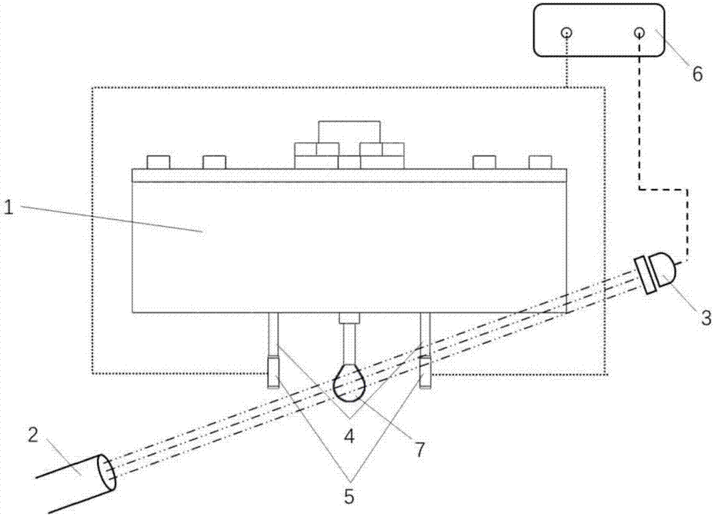
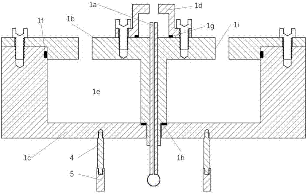
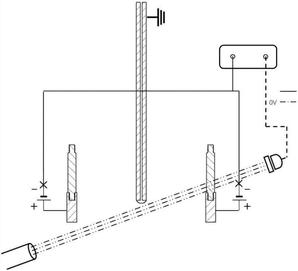
[0036] join figure 1As shown, a droplet generator is disclosed. The droplet generator includes a droplet generator main body 1 , a constant light source 2 , a photodetector 3 , an electrode plate 5 and a pulse high voltage power supply 6 . The droplet generator 1 includes a grounded stainless steel capillary, and a sealed water bath is arranged around the upper part of the stainless steel capillary. The charging properties of the electrode plates 5 are the same after being energized and can be connected to the main body 1 of the droplet generator through the insulating post 4. The electrode plates 5 are placed on both sides of the droplet outlet, and the pulsed high-voltage power supply 6 can be controlled by timing Give the electrode plate a momentary high voltage of kV level as needed. The constant point light source 2 is irradiated at the bottom of the droplet generator main body 1 capillary, that is, the outlet of the suspended droplet, and the constant point light sourc...


PUM


Abstract

The invention provides a droplet generator and a droplet preparation method and relates to the technical fields of liquid micronization and droplet preparation. The droplet generator comprises a droplet generator main body, a normal-bright point light source, a photodetector, electrode plates and a high voltage pulse power supply; the droplet generator main body contains a grounded stainless steel capillary tube; sealed water baths are arranged at the periphery of the stainless steel capillary tube; the normal-bright point light source shares one wire with the stainless steel capillary tube and the photodetector; the electrode plates are fixed on the two sides of an outlet of the stainless steel capillary tube through insulation connecting rods respectively; and the high voltage pulse power supply can send out transient pulse voltage through an external trigger signal of the photodetector and transfers the transient pulse voltage to the two electrode plates at the same time, and polar droplets rapidly drop when growing to fixed size. The droplet generator and the droplet preparation method can be suitable for controlling generation of signal droplet under extreme environment conditions.

Description

technical field [0001] The invention relates to the technical field of liquid micronization and droplet manufacturing, in particular to a droplet generator suitable for extreme environments and a working method thereof. Background technique [0002] The atomization and evaporation characteristics of liquid fuel spray are crucial to the performance of equipment such as spraying, pharmaceuticals, powder metallurgy, and pesticide spraying, especially various engines (liquid rocket engines, ramjet engines, internal combustion engines, gas turbines, and aeroengines, etc.) . For example, for a high-pressure direct-injection engine, the movement, secondary crushing, evaporation, and mixing characteristics of the small droplets produced after spray atomization with the high-speed swirling airflow under high-temperature and high-pressure environmental conditions directly determine the The combustion and emission performance of the engine, the visual experimental research on it, has ...

Claims


Application Information

Patent Timeline
Patent Type & Authority Applications(China)
IPC IPC(8): G01N1/28G01N15/00
CPCG01N1/28G01N15/00
Inventor 李世琰齐飞王轶尊
Owner SHANGHAI JIAO TONG UNIV
Why Eureka
Try Eureka