Spectrally shaped random signal

A technology of random signal and spectrum shaping, applied in random number generators, pulse generators with predetermined statistical distribution of parameters, instruments, etc., can solve problems such as error-prone, large-scale, and expensive

Inactive Publication Date: 2017-09-12
INFINEON TECH AG
View PDF9 Cites 0 Cited by
  • Summary
  • Abstract
  • Description
  • Claims
  • Application Information

AI Technical Summary

Problems solved by technology

But such an application may have a large number of components and thus be expensive and error-prone

Method used


Image

  • Spectrally shaped random signal
  • Spectrally shaped random signal
  • Spectrally shaped random signal

Examples


Embodiment Construction

[0029] The present invention is further explained below with reference to the accompanying drawings and according to preferred embodiments. In these drawings, the same reference numerals denote the same or similar elements. The figures are schematic representations of different embodiments of the invention. Elements shown in these drawings are not necessarily drawn to scale. Rather, the different elements shown in the figures are reproduced such that their function and general use will be apparent to the skilled person. The connections and couplings between functional units and elements shown in these figures can also be realized as indirect connections or couplings. The connection or coupling can be done in a wired or wireless manner. The functional units can be realized as hardware, software or a combination of hardware and software.

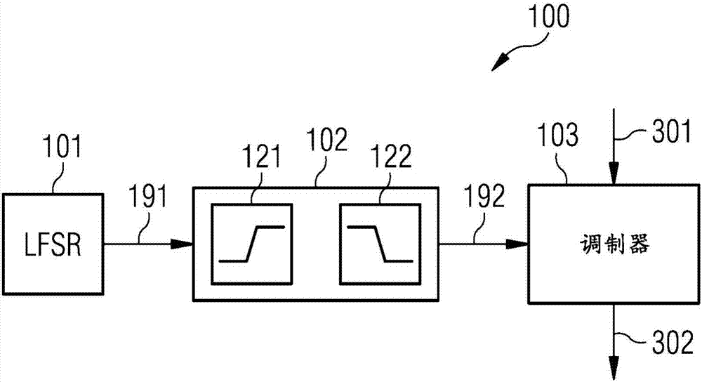
[0030] Different techniques are described below to reduce unwanted components of the modulator's output spectrum due to spikes. The modu...


PUM


Abstract

An apparatus (100) comprises a signal generator (101) that is set up to produce a digital random signal (191). The apparatus (100) also comprises at least one filter element (102, 121, 122) that is set up to apply a high pass filter and a low pass filter to the digital random signal (191) in order to produce a spectrally shaped random signal (112). The apparatus (100) also comprises a modulator (103) that is set up to apply the spectrally shaped random signal (192) as dither.

Description

technical field [0001] Various embodiments relate to a device that includes a signal generator that is configured to generate a digital pseudo-random signal. The device also includes at least one filter element arranged to apply a high-pass filter and a low-pass filter to the digital pseudo-random signal to thus generate a spectrally shaped pseudo-random signal. The device also includes a modulator, which is set up to use the spectrally shaped pseudo-random signal as dither. Various embodiments relate to a corresponding method. Background technique [0002] Modulators, such as analog-to-digital converters (ADCs) or digital modulators, typically generate quantization noise. This quantization noise can cause undesired components in the output spectrum, so-called spikes, which are sometimes also called idle tones. This quantization noise generally causes a degradation in the quality of the modulator. [0003] Techniques for reducing such undesired components of quantization...

Claims


Application Information

Patent Timeline
IPC IPC(8): G06F7/58
CPCG06F7/582G06F7/588H03M1/0641H03M3/50H03M3/33H03K3/84H03M1/0854
Inventor D·斯特雷尤斯尼格
Owner INFINEON TECH AG
Why Eureka
Try Eureka