Enhanced secondary flow-based inertial focus chip

A secondary flow and enhanced technology, applied in the field of microfluidics, can solve the problem of low guiding efficiency of a single secondary flow, and achieve the effect of ensuring success rate, improving strength and enhancing guiding effect

Active Publication Date: 2017-09-15
NORTHWESTERN POLYTECHNICAL UNIV
View PDF4 Cites 6 Cited by
  • Summary
  • Abstract
  • Description
  • Claims
  • Application Information

AI Technical Summary

Problems solved by technology

[0003] In order to solve the problem of low guiding efficiency of a single secondary flow in the existing inertial focusing method, the present invention provides an inertial focusing method capable of increasing the intensity of the secondary flow

Method used


Image

  • Enhanced secondary flow-based inertial focus chip
  • Enhanced secondary flow-based inertial focus chip
  • Enhanced secondary flow-based inertial focus chip

Examples


Embodiment 1

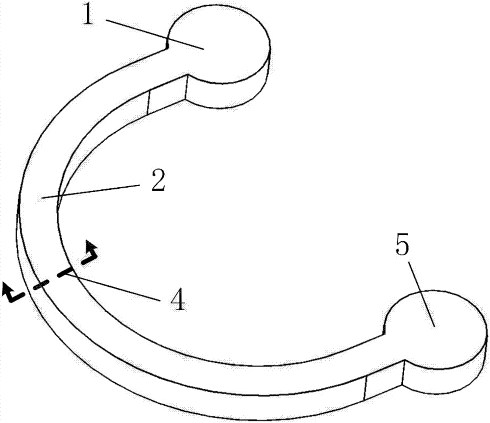
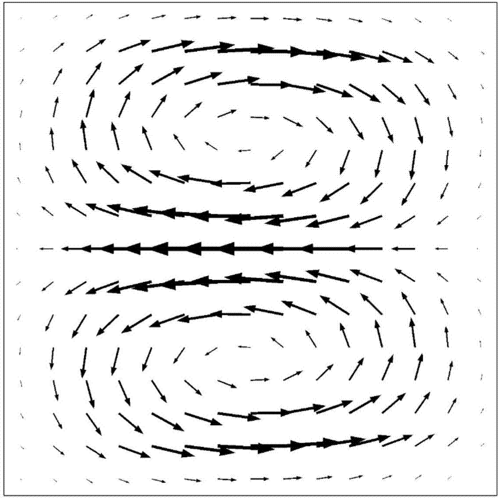
[0025] In this embodiment, the inertial focusing chip based on the enhanced secondary flow is formed by bonding two chip layers. Refer to Figure 5 , one of them has a microchannel on the bonding surface of the chip layer, the two ends of the microchannel are respectively connected to the inlet 1 and the outlet 5, and the main channel is a circular microchannel 2, which produces the first secondary flow (Dean flow ); there are several boss structures distributed on the channel wall, which are square in shape, so that the channel is a variable cross-section channel, which produces the second secondary flow (the secondary flow caused by the geometric structure); the boss structure is located in the channel The curved surface of the wall is a convex side, so that the first secondary flow is in the same direction as the second secondary flow; the material of the microfluidic focusing chip is polydimethylsiloxane (PDMS), polymethylmethacrylate ( PMMA), polycarbonate (PC) or glass, ...

Embodiment 2

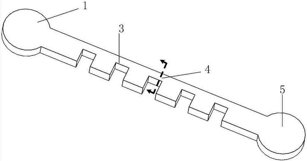
[0039] In this embodiment, the inertial focusing chip based on the enhanced secondary flow is formed by bonding two chip layers. Refer to Figure 10 , one of them has a microchannel on the bonding surface of the chip layer, and the two ends of the microchannel are respectively connected to the inlet 1 and the outlet 5, and the main channel is a curved microchannel, which produces the first secondary flow (Dean flow); There are several boss structures distributed on the wall of the channel, which are cylindrical in shape, so that the channel is a channel with variable cross-section, which generates the second secondary flow (secondary flow caused by geometric structure); the boss structure is located on the channel wall. The curved surface is a convex side, so that the first secondary flow is in the same direction as the second secondary flow; the microfluidic focusing chip material is polydimethylsiloxane (PDMS), polymethylmethacrylate (PMMA ), polycarbonate (PC) or glass, etc...


PUM


Abstract

The invention discloses an enhanced secondary flow-based inertial focus chip and belongs to the technical field of microflow control. The chip is formed by bonding two chip layers, wherein a microchannel is formed on one chip layer bonding surface; and two ends of the microchannel are respectively connected with an inlet and an outlet. The enhanced secondary flow-based inertial focus chip is characterized in that the microchannel is a channel with curvature, and the channel with the curvature generates a first secondary flow (Dene flow); and a plurality of lug boss structures are distributed on the wall surface of the channel, so that the channel is a variable cross section channel and generates a second secondary flow (secondary flow caused by a geometric structure). The microflow control chip can be used for sorting, separation, counting and detection of particles or cells and is also applicable to occasions, such as fluid mixing and sample pre-processing. Two secondary flows are generated during flowage of fluids through the inertial focus chip which simultaneously adopts two secondary flows, meanwhile, directions of the two secondary flows are enabled to be the same, the two secondary flows are overlapped, the strength of the secondary flows is enhanced, and a guidance effect of the secondary flows is enhanced.

Description

technical field [0001] The invention belongs to the technical field of microfluidics, and in particular relates to an inertial focusing microfluidics chip. Background technique [0002] The document "Three dimensional, sheathless, and high‐throughput microparticle inertial focusing through geometry‐induced secondary flows[J]. Small, 2013, 9(5): 685-690." discloses an inertial focusing through geometry‐induced secondary flows. Focus chip. The chip adopts a microchannel structure with a step on one side. The channel section has a sudden change at the edge of the step, and the fluid in the channel will bend at the sudden change to form a curved flow, thereby generating a secondary flow caused by the geometric structure. At the same time, due to the inertial effect, the particles in the microchannel are affected by the fluid flow, and after a certain length of movement, they will gradually migrate to certain fixed positions. Through the guiding effect of the secondary flow and...

Claims


Application Information

Patent Timeline
Patent Type & Authority Applications(China)
IPC IPC(8): B01L3/00
CPCB01L3/502746B01L3/502761B01L2200/0636B01L2200/0694B01L2300/0861B01L2300/12B01L2400/0403B01L2400/086
Inventor 常洪龙冯建国寻文鹏
Owner NORTHWESTERN POLYTECHNICAL UNIV
Why Eureka
Try Eureka