Solid wireframe modeling device

A wireframe and entity technology, applied in manufacturing auxiliary devices, processing and manufacturing, processing data acquisition/processing, etc., can solve the problems of unsuitable large-scale entity wireframe integrated modeling, troubles, etc., achieve diverse and fast shapes, and facilitate positioning and movement , High stability effect

Inactive Publication Date: 2019-03-29
HUAIYIN INSTITUTE OF TECHNOLOGY
View PDF2 Cites 0 Cited by
  • Summary
  • Abstract
  • Description
  • Claims
  • Application Information

AI Technical Summary

Problems solved by technology

[0002] 3D printing technology is becoming more and more mature, using computer data model for parameter control to realize layer-by-layer stacking printing modeling, but when performing solid wireframe modeling, traditional 3D printing technology has limitations, and general 3D printing devices are only suitable for For modeling printing of small items, when printing large objects or wireframes, it needs to be printed in sections and then stitched together, causing trouble, or a large-scale dedicated 3D printing device requires a large spatial range of displacement when working , to drive the discharge port to move, although it can adapt to general large-scale printing, but due to the need for assembly and coordination of large accessories such as positioning mobile frames, it will be subject to more restrictions, and it is not suitable for the integrated modeling of large solid wireframes

Method used


Image

  • Solid wireframe modeling device
  • Solid wireframe modeling device
  • Solid wireframe modeling device

Examples


Embodiment Construction

[0030] The present invention will be further described in detail below in conjunction with the accompanying drawings and specific embodiments.

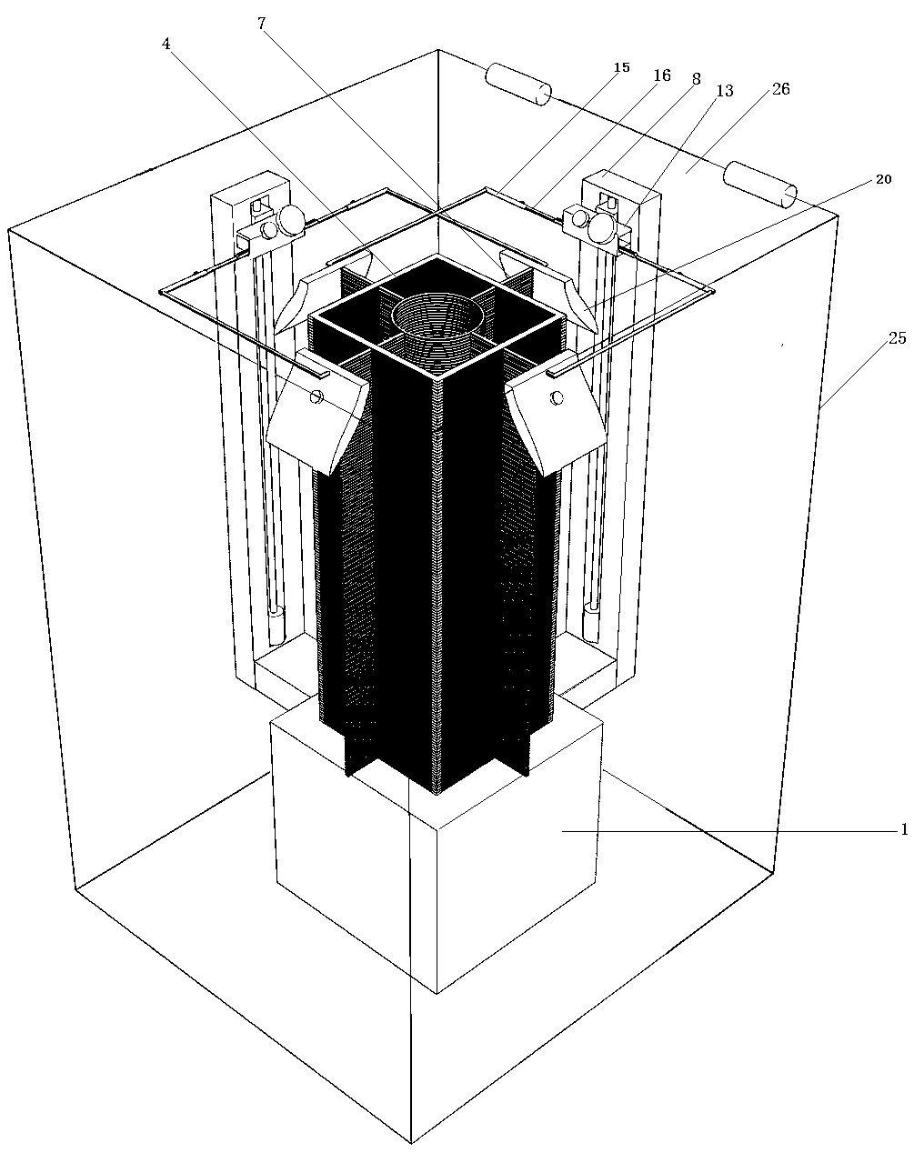
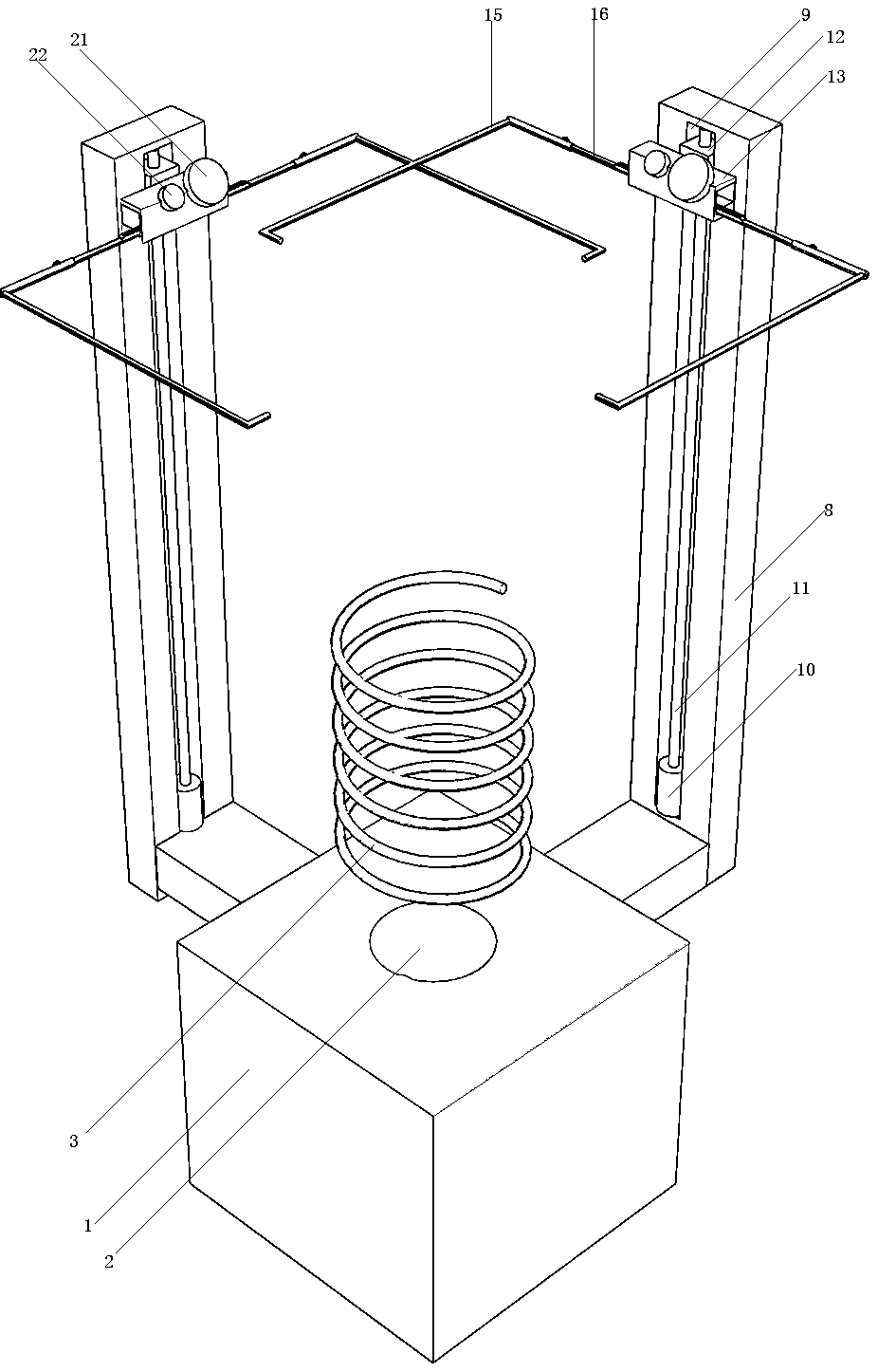
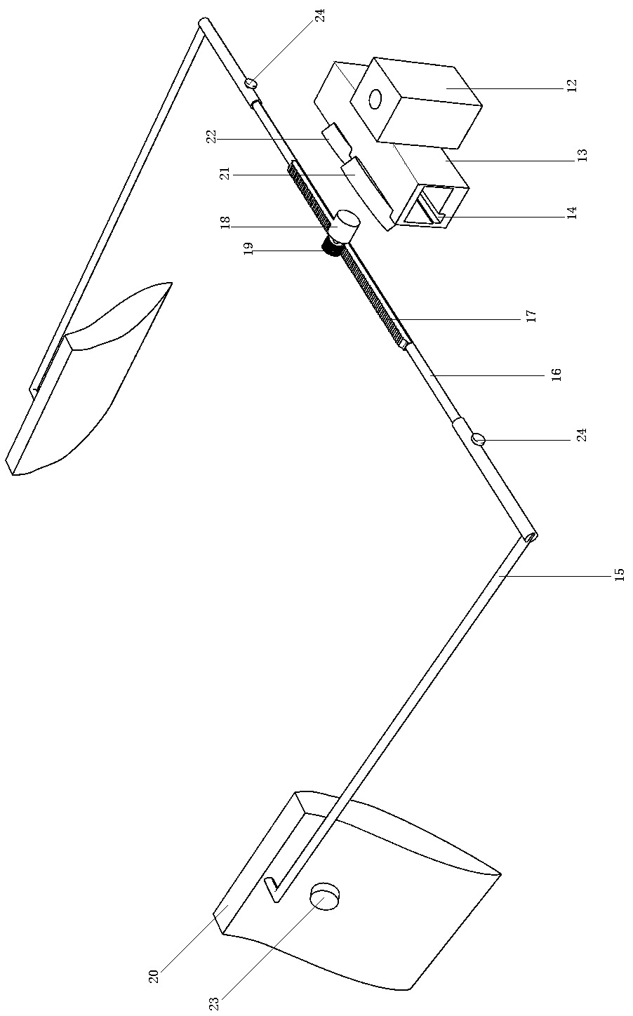
[0031] Such as Figure 1-7As shown, the solid wire frame molding device includes a heating and feeding device below and a molding mechanism above; the molding mechanism includes two automatic positioning devices and several positioning molding devices arranged up and down; a heat dissipation device is installed on the automatic positioning device The heating and feeding device includes a lower base shell 1; the base shell 1 has a feeding hole 2; the inner middle of the base shell 1 is equipped with a heating resistance wire 3; the positioning molding device includes a square frame 4; The middle part of the frame 4 is provided with a molding frame 5; the four sides of the frame 4 are provided with horizontally penetrating chutes 6; the positioning control board 7 is slidably connected in the chute 6; the inner ends of the positioning c...


PUM


Abstract

The invention discloses a solid wireframe modeling device, and relates to the technical field of solid wireframe modeling. The solid wireframe modeling device comprises a heating feed device on the lower portion and a modeling mechanism on the upper portion. The modeling mechanism comprises two automatic positioning devices and multiple locating modeling devices arranged up and down. Each locating modeling device comprises a square frame. A modeling frame is arranged in the middle of each square frame. The structures of the two automatic positioning devices are the same, and the two automatic positioning devices are located in front of and on the right portion of the locating modeling devices correspondingly. The automatic positioning device on the right portion comprises a vertical mounting shell. A guide groove is formed in the bottom end in a guide shell. A U-shaped swing rod is in sliding connection in the guide groove. The front side and the rear side of the swing rod are fixedly connected with locating push plates. A heat radiation device comprises a heat radiation fan mounted on the guide shell. The solid wireframe modeling device has the beneficial effects that a raw material wire is subjected to modeling through computer control, the modeling speed is high, and the solid wireframe modeling device is suitable for being used for large solid wireframe modeling.

Description

technical field [0001] The invention relates to the technical field of solid wireframe modeling. Background technique [0002] 3D printing technology is becoming more and more mature, using computer data model for parameter control to realize layer-by-layer stacking printing modeling, but when performing solid wireframe modeling, traditional 3D printing technology has limitations, and general 3D printing devices are only suitable for For modeling printing of small items, when printing large objects or wireframes, it needs to be printed in sections and then stitched together, causing trouble, or a large-scale dedicated 3D printing device requires a large spatial range of displacement when working , to drive the discharge port to move, although it can adapt to general large-scale printing, but due to the need for assembly and coordination of large accessories such as positioning mobile frames, it will be subject to more restrictions, and it is not suitable for the integrated m...

Claims


Application Information

Patent Timeline
Patent Type & Authority Patents(China)
IPC IPC(8): B29C64/10B29C64/30B29C64/393B33Y10/00B33Y30/00B33Y50/02B33Y70/00B33Y80/00
CPCB33Y10/00B33Y30/00B33Y50/02B33Y70/00B33Y80/00
Inventor 张光祥何艳婷吕艳张志强
Owner HUAIYIN INSTITUTE OF TECHNOLOGY
Why Eureka
Try Eureka