

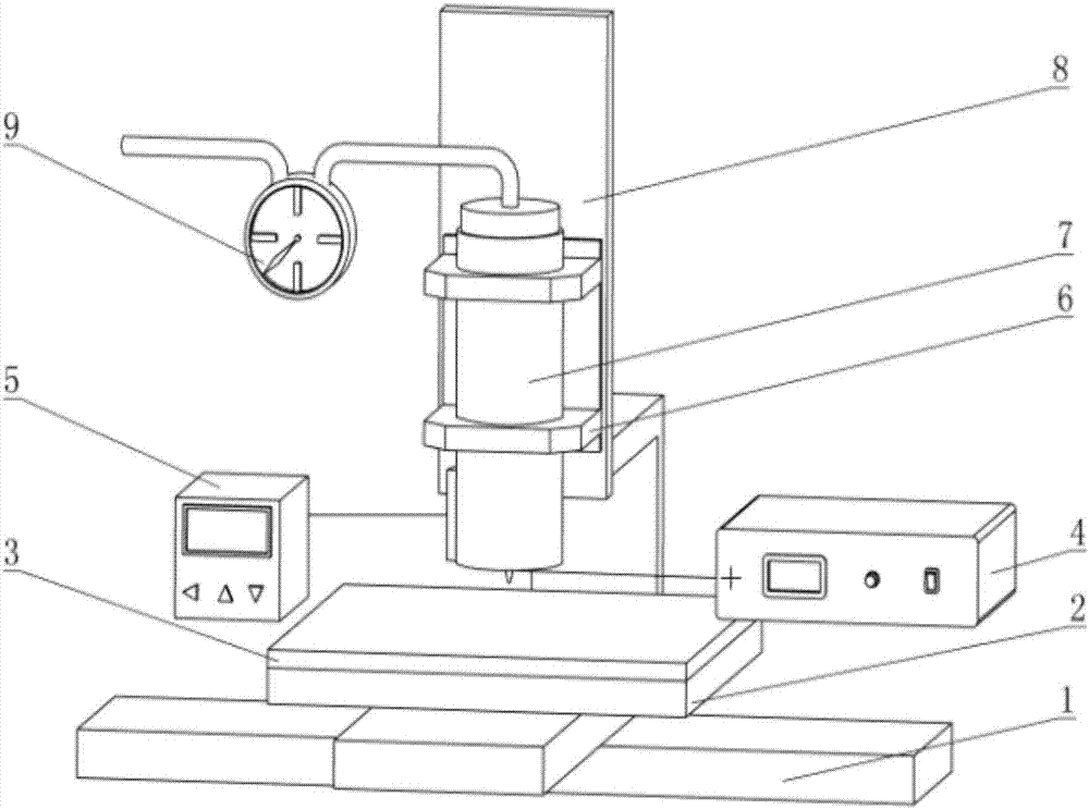
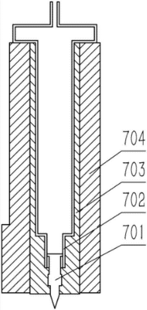
Molten jetting deposition 3D printing device driven by electric field, and working method thereof
A printing device and spray deposition technology, applied in the direction of coating devices, manufacturing auxiliary devices, 3D object support structures, etc., can solve the problems of difficult to realize large-scale parts manufacturing, low printing accuracy and quality, poor performance of manufactured parts, etc. problems, to achieve the effect of improving stability and reliability, avoiding short circuit and breakdown discharge, and taking printing accuracy into account
- Summary
- Abstract
- Description
- Claims
- Application Information
AI Technical Summary
Problems solved by technology
Method used
Image

Examples
Embodiment Construction
[0043] It should be pointed out that the following detailed description is exemplary and intended to provide further explanation to the present application. Unless defined otherwise, all technical and scientific terms used herein have the same meaning as commonly understood by one of ordinary skill in the art to which this application belongs.
[0044] It should be noted that the terminology used here is only for describing specific implementations, and is not intended to limit the exemplary implementations according to the present application. As used herein, unless the context clearly dictates otherwise, the singular is intended to include the plural, and it should also be understood that when the terms "comprising" and / or "comprising" are used in this specification, they mean There are features, steps, operations, means, components and / or combinations thereof.
[0045] As introduced in the background technology, the existing technology has the problems of low precision of ...
PUM
 Abstract
Description
Claims
Application Information