
Burning stabilizing ring structure of vortex burner

A burner and swirling technology, applied in the direction of burners, burners burning powder fuel, combustion methods, etc., can solve problems such as short service life, unsafe boilers, falling off, etc., to improve safety and economy, Does not affect the mechanical strength, easy to replace and install

Inactive Publication Date: 2017-09-15
JIANGSU JINGCHENG MASCH MFG CO LTD
View PDF5 Cites 1 Cited by
  • Summary
  • Abstract
  • Description
  • Claims
  • Application Information

AI Technical Summary

Problems solved by technology

[0008] At present, the swirling flow burners used in power plant boilers have shortcomings such as serious coking, high nitrogen oxide emissions, easy burning of the nozzle, deformation of the stable combustion ring, and loss of stable combustion teeth due to the uneven quality of domestic thermal coal.
[0009] In the past, the combustion-stabilizing ring and the combustion-stabilizing tooth were integrally cast with the same material. Due to the different temperature and airflow erosion environment, the combustion-stabilizing tooth was often severely worn, the combustion-stabilizing ring was deformed and damaged, and the combustion-stabilizing tooth was cracked and fell off. Short service life seriously affects the safe operation of the boiler and increases the maintenance cost of the power plant
In particular, the combustion stabilizing gear is the most important part of the combustion stabilization ring, and the wear or burnout of the combustion stabilization ring will greatly affect the overall performance of the burner, which will bring great unsafe factors to the boiler

Method used


Image

  • Burning stabilizing ring structure of vortex burner
  • Burning stabilizing ring structure of vortex burner
  • Burning stabilizing ring structure of vortex burner

Examples


Embodiment Construction

[0022] The specific implementation manners of the present invention will be described in detail below in conjunction with the accompanying drawings.

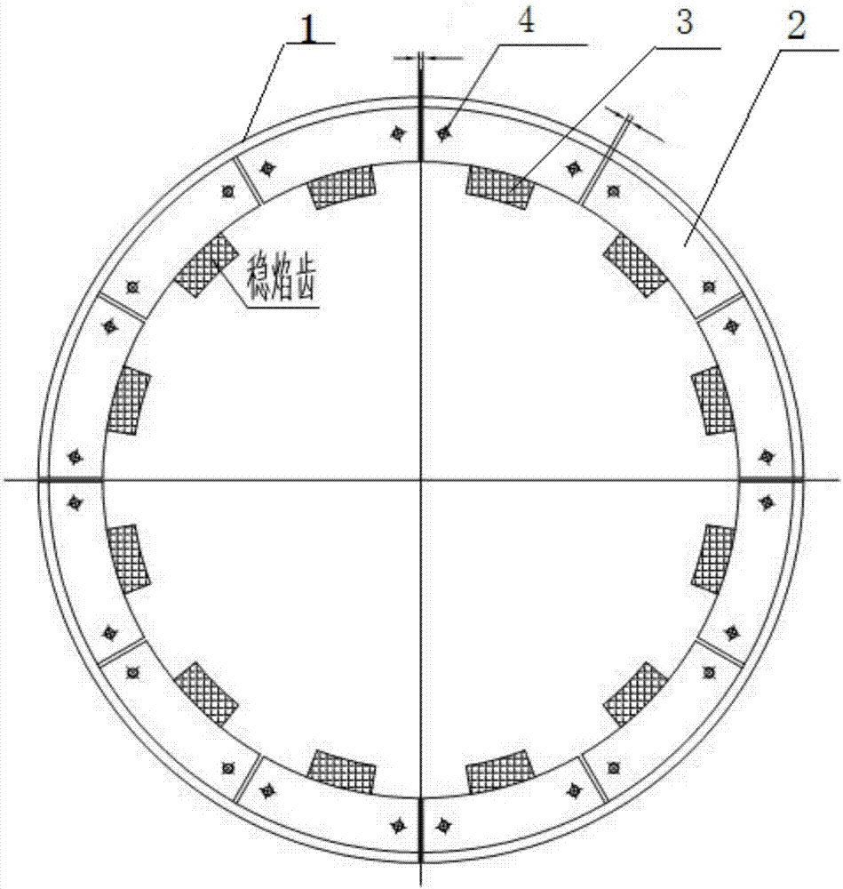
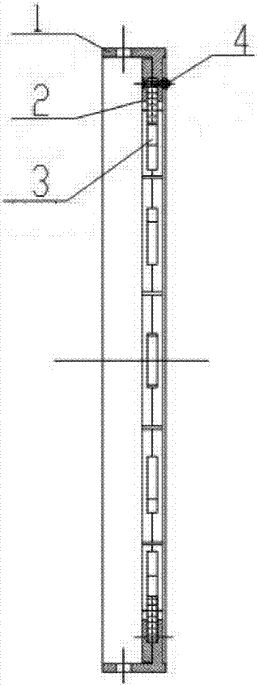
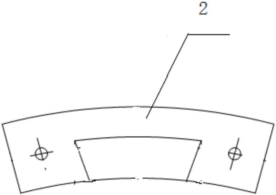
[0023] like figure 1 figure 2 As shown, the flame stabilizing ring structure of the swirl burner of the present invention includes a flame stabilizing ring body 1, a dry flame stabilizing tooth 3, a pressure plate 2, and a bolt assembly 4, and the flame stabilizing tooth 3 is pressed by the pressure plate 2 on the stable flame On the burning ring body, the pressure plate 2 is arranged on the stable burning ring body, and its shape matches the stable burning ring body. The bolt assembly 4 passes through the stable burning ring body 1, the pressing plate 2 and the flame stabilizing tooth 3, so that the flame stabilizing tooth 3 Fixed on the combustion-stabilizing ring body, the flame-stabilizing teeth 3 are evenly spaced on the combustion-stabilizing ring body, and the silicon carbide stabilizing teeth are evenly distributed alo...


PUM


Abstract

The invention discloses a burning stabilizing ring structure of a vortex burner. The burning stabilizing ring structure comprises a burning stabilizing ring body and further comprises a plurality of flame stabilizing teeth, a pressing plate and a bolt assembly. The flame stabilizing teeth are pressed to the burning stabilizing ring body through the pressing plate. The pressing plate is arranged on the burning stabilizing ring body. The bolt assembly penetrates through the burning stabilizing ring body, the pressing plate and the flame stabilizing teeth, so that the flame stabilizing teeth are fixed to the burning stabilizing ring body at equal intervals, and the windward faces of the flame stabilizing teeth are made from silicon carbide. The silicon burning stabilizing ring can resist high temperature and abrasion, the burning stabilizing teeth can be effectively prevented from falling off, the service life of the burner is prolonged, and safety and economy of a power plant are improved.

Description

technical field [0001] The invention belongs to the technical field of swirl burners in power plants, and in particular relates to a low-nitrogen oxide and low-load stable combustion device for swirl burners. Background technique [0002] The stable combustion ring device is installed at the outlet end of the primary air duct of the swirl burner. When the pulverized coal flow passes through the device, the pulverized coal particles gather toward the outer ring of the primary air duct to increase the concentration of pulverized coal, effectively reduce the amount of NOx generated, and reduce the Fiery heat is conducive to timely ignition and stable combustion of pulverized coal airflow at low load and when low-quality coal is used. [0003] The swirl burner with flame-stabilizing teeth is equipped with a flame-stabilizing ring, which is used to strengthen the ignition of the pulverized coal airflow. The combustion-supporting air is divided into two streams to realize the sta...

Claims


Application Information

Patent Timeline
Patent Type & Authority Applications(China)
IPC IPC(8): F23D1/02
CPCF23D1/02
Inventor 丁宇姚圣余刘家宝曾小弟
Owner JIANGSU JINGCHENG MASCH MFG CO LTD
Learn More