Energy absorber

An energy absorber and absorbing structure technology, applied in the field of integrated optics, can solve problems such as low spectral width, high requirements for structural parameters, and instability, and achieve low processing technology requirements, simple structural design, and large processing errors. Effect

Active Publication Date: 2017-09-15
UNIV OF SCI & TECH OF CHINA
View PDF4 Cites 3 Cited by
  • Summary
  • Abstract
  • Description
  • Claims
  • Application Information

AI Technical Summary

Problems solved by technology

[0002] Traditional energy absorbers mostly use resonant cavity schemes to eliminate reflection and transmission. However, the resonant cavity must work under the condition of critical coupling, and the structural parameters of the cavity are very high. The absorption spectrum of the resonant cavity is Loren The spectral width is relatively low, and the resonant center wavelength of the resonant cavity is very sensitive to temperature. After working for a period of time, the energy stored in the cavity will cause the temperature to rise, which will cause instability. It takes time to start a stable oscillation, so it is not conducive to the application of ultrafast pulse correlation. In particular, in the integrated optical circuit, the energy is usually a mode of specific polarization. For the same resonant cavity structure, its resonance peaks are usually different, so it is difficult to realize Simultaneous absorption of two polarizations

Method used


Image

  • Energy absorber
  • Energy absorber
  • Energy absorber

Examples


experiment example 1

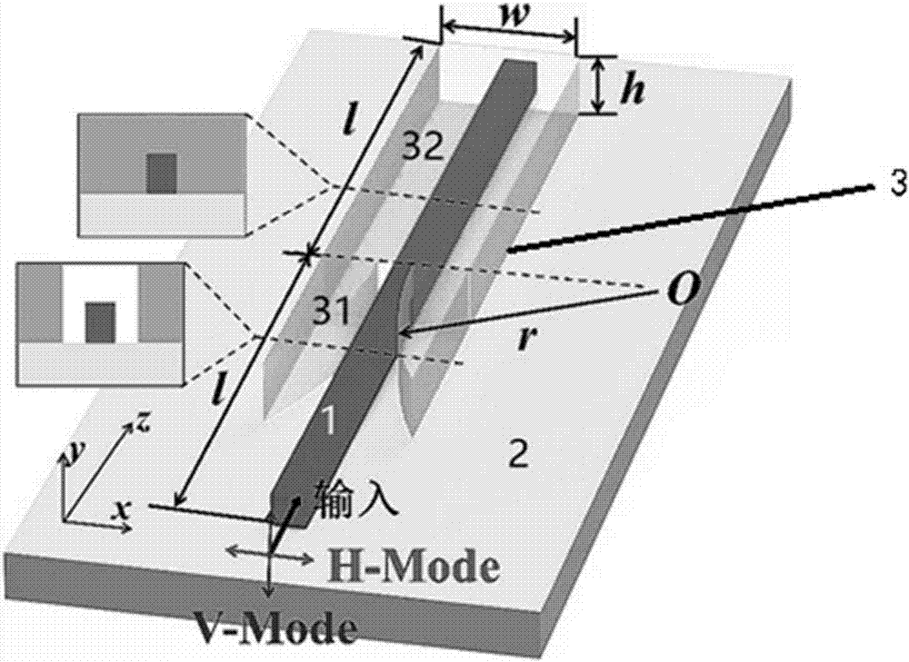
[0036] An energy absorber was designed by applying the above scheme, so that the length of the metal absorbing structure 31 is l=20 μm, the metal material is gold (Au), and the rectangular cross-sectional size of the metal absorbing structure is 1.5 μm×0.8 μm.

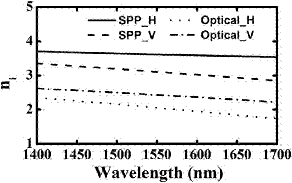
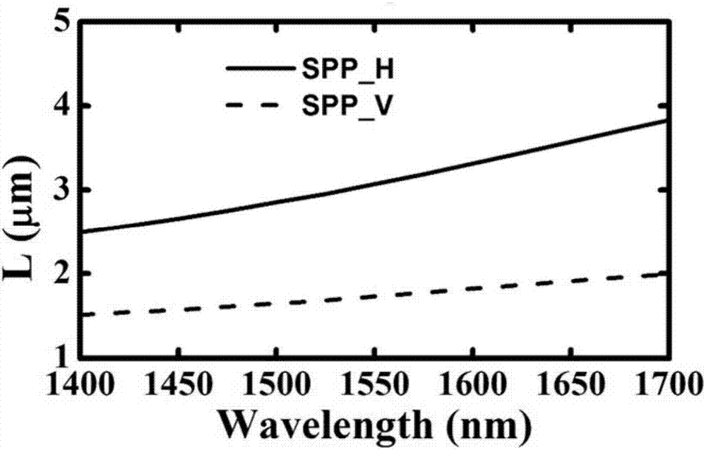
[0037] Any propagating field in a dielectric optical waveguide can be regarded as a linear superposition of all eigenmodes, which is similar to Fourier series in form, where the proportion of each eigenmode in the total electric field is recorded as C(n i ), known as the weighting factor, n i is the effective refractive index of the eigenmode. The weight factor of each eigenmode can be obtained by Fourier transforming the total electric field E(z) on the central axis of the waveguide, where n i The preceding symbol represents the direction of energy propagation.

[0038] Figure 4 It is the Fourier transform spectrogram of the metal adiabatic structure in an experimental example of the present invention and the rela...


PUM

PropertyMeasurementUnit
reflectanceaaaaaaaaaa
transmittivityaaaaaaaaaa

Abstract

The invention provides an energy absorber comprising a dielectric optical waveguide which is used for transmitting photons; and a metal wrapping layer which comprises a metal absorption structure in which the metal layer completely wraps the dielectric optical waveguide.

Description

technical field [0001] The invention relates to the technical field of integrated optics, in particular to an energy absorber. Background technique [0002] Traditional energy absorbers mostly use resonant cavity schemes to eliminate reflection and transmission. However, the resonant cavity must work under the condition of critical coupling, and the structural parameters of the cavity are very high. The absorption spectrum of the resonant cavity is Loren The spectral width is relatively low, and the resonant center wavelength of the resonant cavity is very sensitive to temperature. After working for a period of time, the energy stored in the cavity will cause the temperature to rise, which will cause instability. It takes time to start a stable oscillation, so it is not conducive to the application of ultrafast pulse correlation. In particular, in the integrated optical circuit, the energy is usually a mode of specific polarization. For the same resonant cavity structure, it...

Claims


Application Information

Patent Timeline
Patent Type & Authority Applications(China)
IPC IPC(8): G02B6/12
CPCG02B6/12G02B2006/12126
Inventor 熊霄邹长铃任希锋郭光灿
Owner UNIV OF SCI & TECH OF CHINA
Why Eureka
Try Eureka