Combination converter capable of realizing output tight adjustment

A converter and tight adjustment technology, applied in output power conversion devices, regulating electrical variables, instruments, etc., can solve problems such as reducing power density and increasing cost, reducing the number of magnetic cores, improving efficiency and power density, Topologically simple effects

Active Publication Date: 2017-09-15
ZHEJIANG UNIV
View PDF5 Cites 6 Cited by
  • Summary
  • Abstract
  • Description
  • Claims
  • Application Information

AI Technical Summary

Problems solved by technology

However, an independent auxiliary transformer needs to be added in t

Method used


Image

  • Combination converter capable of realizing output tight adjustment
  • Combination converter capable of realizing output tight adjustment
  • Combination converter capable of realizing output tight adjustment

Examples


Embodiment 1

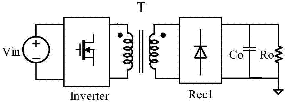
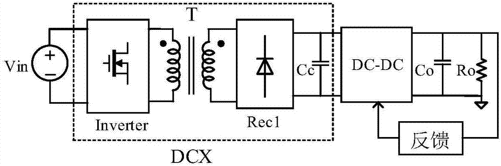
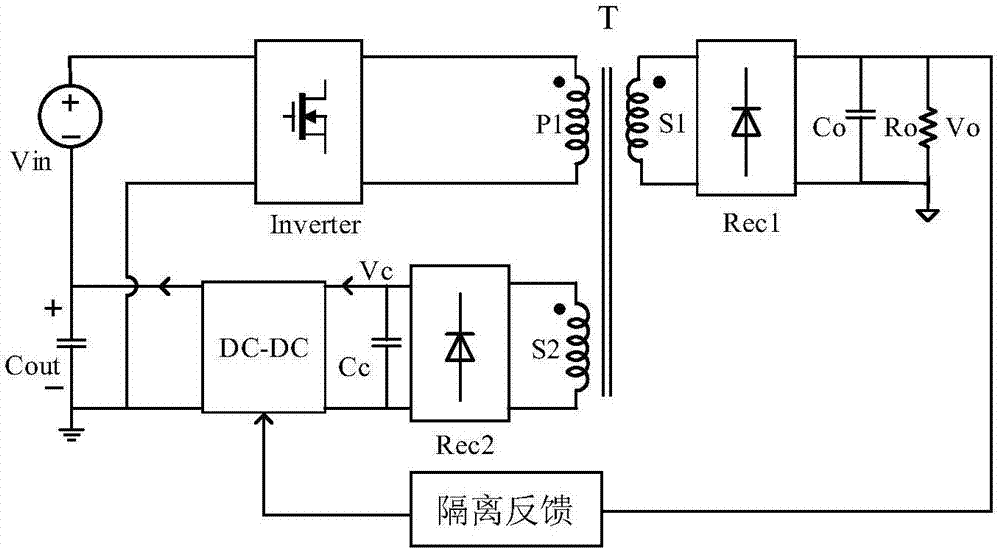
[0042] The combined converter with tightly regulated output includes an input DC voltage Vin, a transformer T, a high-frequency inverter circuit Inverter located on the primary side of the transformer, an output winding S1 located on the secondary side of the transformer, and a first rectifier circuit Rec1. The circuit Rec1 is connected to the output capacitor Co; the primary side winding of the transformer T is composed of the first winding P1 and the auxiliary winding S2, wherein the first winding P1 is connected to the output of the high-frequency inverter circuit Inverter, and the auxiliary winding S2 is rectified by the second The circuit Rec2 is connected to the non-isolated DC-DC conversion circuit; the output capacitor Cout of the non-isolated DC-DC conversion circuit is connected in series with the input DC voltage Vin, and the output of the input DC voltage Vin is used as the DC input of the high-frequency inverter circuit Inverter; The DC output voltage Vo is sampled...

Embodiment 2

[0045] In order to keep the input voltage of the high-frequency inverter circuit Inverter stable, an input capacitor Cin is connected in parallel on its input side, such as Figure 4 shown. The structure of the rest of the circuit is the same as that in Embodiment 1, and will not be repeated here.

Embodiment 3

[0047] In order to meet the requirement that no back pressure is generated at both ends of the non-isolated DC-DC output capacitor Cout at the start-up moment, a diode D is connected in antiparallel to both ends of the output capacitor. After the circuit starts, the diode D bears the back pressure without affecting the normal operation of the circuit, such as Figure 5 shown. The structure of the rest of the circuit is the same as that in Embodiment 2, and will not be repeated here.


PUM


Abstract

The invention relates to an isolation type DC/DC power converter and is to provide a combination converter capable of realizing output tight adjustment. A primary side winding of a transformer is formed by a first winding and an auxiliary winding, wherein the first winding is connected with the output of an inverter circuit, and the auxiliary winding is connected to an un-isolated DC-DC converting circuit through a second rectifier circuit; an output capacitor of the un-isolated DC-DC converting circuit is connected in series with an input DC voltage to serve as DC input of the inverter circuit; a DC output voltage is sampled on a resistor connected in parallel to the output capacitor and sent to an isolation feedback circuit; and the isolation feedback circuit sends a duty ratio regulation signal to the un-isolated DC-DC converting circuit to realize tight adjustment of the output voltage. Magnetic core utilization rate of the transformer can be maximized, and efficiency and power density are improved; stability and regulation of the output voltage can be realized without changing switching frequency of a resonance circuit; only one main isolation transformer is needed in the topology, thereby reducing magnetic core quantity; and the rectifier circuit at the secondary side of the transformer can adopt the synchronous rectification technology easier.

Description

technical field [0001] The invention relates to an isolated DC / DC electric energy converter, in particular to a combined converter with tightly regulated output. Background technique [0002] Many power conversion applications require electrical isolation between the input and output, and tight adjustment of the output voltage to ensure that the output voltage remains constant when the load is disturbed or the input voltage changes. In order to achieve tight adjustment of the output, a DC / DC converter with high-frequency transformer isolation is generally used, such as figure 1 As shown, the output voltage can be kept constant by adjusting the duty ratio of the primary switching tube or the switching frequency. Although such a solution is simple, the efficiency is low, especially the working duty cycle of the transformer will also change with the duty cycle adjustment of the circuit, resulting in low utilization efficiency of the transformer. [0003] In order to improve t...

Claims


Application Information

Patent Timeline
IPC IPC(8): H02M3/335
CPCH02M3/335H02M1/007Y02B70/10
Inventor 吴新科康培林
Owner ZHEJIANG UNIV
Why Eureka
Try Eureka